Advertisement
Quick Links
Download this manual
See also:
User Manual
THERMOPROZESS
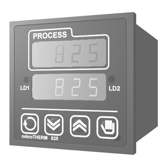
MIKROTHERM
825
®
MT825-A,
Communications
THERMOPROZESS s.r.o.
Riegrova 2668/6c
370 01 České Budějovice
tel.: +420 387 313 182
fax : +420 385 340 947
e-mail:
info@thermoprozess.cz
MT825A/C 11/09 Rev.3/Soft.4
internet :
www.thermoprozess.cz
Advertisement

Related Manuals for thermoprozess MIKROTHERM 825

Summary of Contents for thermoprozess MIKROTHERM 825
- Page 1 THERMOPROZESS MIKROTHERM ® MT825-A, Communications THERMOPROZESS s.r.o. Riegrova 2668/6c 370 01 České Budějovice tel.: +420 387 313 182 fax : +420 385 340 947 e-mail: info@thermoprozess.cz MT825A/C 11/09 Rev.3/Soft.4 internet : www.thermoprozess.cz...
- Page 2 C o m m u n i c a t i o n s 1 Scope of communications Communication line enhances usability of the controller from autonomous controller to the one which performs the tasks in a system. Basic feasibilities are described in the 5 following articles: •...
- Page 3 C o m m u n i c a t i o n s 2 Communication interfaces The controllers can be equipped with communication interface RS 232 or EIA 485. The baudrate of the communication is permanently set at 9600 Bd, the data bits is 8, no parity, 1 stopbit.
- Page 4 C o m m u n i c a t i o n s 3 Protocol MODBUS The communication protocol MODBUS is intended for creating networks of type „Master – Slave“, when „Master“ is PC, „Slave“ are always controllers. Its characteristic is simple, but reliable structure with these features: •...
- Page 5 C o m m u n i c a t i o n s 3.3 Operation - write (06H) This operation enables writing a value to 1 register of controller: Command: Address of Address of register Data controller 1 byte 1 byte 2 bytes (1.
- Page 6 C o m m u n i c a t i o n s Command: Address of Data controller 1 byte 1 byte 4 bytes 2 bytes Response: Address of Data controller 1 byte 1 byte 4 bytes 2 bytes Example: back inquiry, controller at the address 12 (0CH) Command: Response:...
- Page 7 C o m m u n i c a t i o n s 4 Overview of registers The table comprises the total overview of registers that are accessible for communication line. The meaning of particular parameters is the following: •...
- Page 8 C o m m u n i c a t i o n s Display Address Range Initiation Dec. point Note 12 r/w 0 … oFF Start on, stop automatic setting of PID 1 … parameters 50 r Process value dEC1 If sensor is not set, the controller returns the value –22000.
- Page 9 C o m m u n i c a t i o n s Operation level Display Address Range Initiation Dec. point Note 100 r/w SP1L to SP1h Set point value, reading appears on lower display dEC1 110 r/w 10 to 24990 Proportional band 111 r/w 0 to 999...
- Page 10 C o m m u n i c a t i o n s Configuration level Display Address Range Initiation Dec. point Note 200 r/w Thermocouple input: Setting of the input sensor 0 … 1 … 2 … 3 … 4 …...
- Page 11 C o m m u n i c a t i o n s Display Address Range Initiation Dec. point Note 220 r/w 0 … Setting of alarm / signal output 1 … ALPr 2 … AldE 3 … SGPr 4 …...
- Page 12 C o m m u n i c a t i o n s Display Address Range Initiation Dec. point Note StP1 270 r/w 0 … position of user menu 1 … hISt 2 … run 3 … CLK 4 … PCnt 5 …...
- Page 13 C o m m u n i c a t i o n s Extended configuration menu Display Address Range Initiation Dec. point Note 300 r/w 0 … Ent1 Setting of the function for the output 3 1 … ALPr 2 …...
- Page 14 C o m m u n i c a t i o n s Editing a program Display Address Range Initiation Dec. point Note Prog 1400 r/w 1 to 30 Program for editing StEP 1401 r/w 1 to 15 Step to be edited tyPE 1410 r/w 0 …...
- Page 15 C o m m u n i c a t i o n s Starting a program by the internal clock Display Address Range Initiation Dec. point Note PCLK 1220 r/w 0 to 34 Set number of program you wish to start up 0 …...
- Page 16 C o m m u n i c a t i o n s Reading of measured values, deleting memory Display Address Range Initiation Dec. point Note 1300 r/w 0 to 199 pro RAM 2kB Setting of position for reading data.
- Page 17 C o m m u n i c a t i o n s 5 Index Scope of communications ........................2 Communication interfaces ........................3 Interface RS 232..........................3 Interface EIA 485........................... 3 Protocol MODBUS ..........................4 General structure of protocol......................4 Operation - reading.........................
Need help?
Do you have a question about the MIKROTHERM 825 and is the answer not in the manual?
Questions and answers