Table of Contents
Advertisement
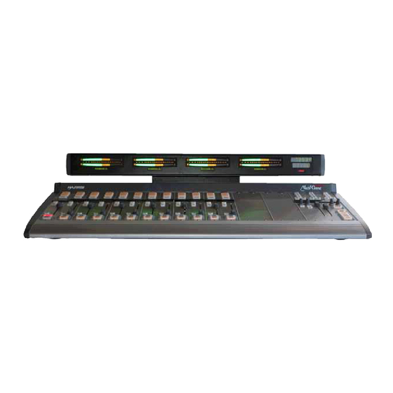
DirectView Broadcast
Console Operations &
Technical Manual
PRE75-60
8 Channel Console with Dual Metering: PRE99-1600D-08
16 Channel Console with Dual Metering: PRE99-1600D-16
16 Channel Console with Quad Metering: PRE99-1600Q-16
24 Channel Console with Dual Metering: PRE99-1600D-24
24 Channel Console with Quad Metering: PRE99-1600Q-24
www.harrisbroadcast.com
Revision A – 3/13
Advertisement
Table of Contents

Summary of Contents for Harris Broadcast NetWave PRE99-1600D-08
-
Page 1: Technical Manual
DirectView Broadcast Console Operations & Technical Manual 8 Channel Console with Dual Metering: PRE99-1600D-08 16 Channel Console with Dual Metering: PRE99-1600D-16 16 Channel Console with Quad Metering: PRE99-1600Q-16 24 Channel Console with Dual Metering: PRE99-1600D-24 24 Channel Console with Quad Metering: PRE99-1600Q-24 PRE75-60 Revision A –... - Page 2 Harris Broadcast shall not be liable for errors You can also call the Customer Support line or send a contained herein or for incidental or non-emergency e-mail: consequential damage in connection with the furnishing, performance, or use of this material.
- Page 3 Cabling & Wiring ..................2-22 Required Cables & Wires ................2-22 Wire Preparation ................... 2-23 Crimp Tool Operation ..................2-24 Audio Connections ..................2-25 Unbalanced Connections ................2-26 NetWave Sample Rate ................... 2-28 Audio Connections ..................2-28 Logic Connections ..................2-29 Harris Broadcast PR&E...
- Page 4 Installation Kits ....................5-2 Optional Upgrade Kits ..................5-3 Control Panel Service................5-3 Control Test Mode ...................5-3 Panel Construction ..................5-4 Control Panel Removal and Installation ..............5-4 Fader Removal and Reinstallation ..............5-5 Console Display Service ................5-6 Console Display Removal .................5-6 Harris Broadcast PR&E...
- Page 5 Mic Remote Control Panels ................6-2 3x6 Headphone Distribution Amp .............. 6-4 ESE/SMPTE Master Clock ................. 6-5 Quad A/D Converter ................6-5 Dual Selector Kit ..................6-6 Link Activation Kits .................. 6-6 Dual Router Kit ..................6-6 NetWave Toolkit ..................6-6 Harris Broadcast PR&E...
- Page 6 Figure 2-35. Cable from a NetWave Logic Connector to a Mic Control Panel ......... 2-32 Figure 2-36. Example of Mic & Mic Control Panel Connected to Channel 2 ..........2-35 Figure 2-37. CD Player Connected to Input 4 ................... 2-36 Harris Broadcast PR&E...
- Page 7 Figure 6-5. Mic Control Panel Cable Diagram ..................6-3 Figure 6-6. PRE99-1215 Headphone Amplifier with NetWave Console ............ 6-4 Figure 6-7. Rear Panel ESE/SMPTE and Timer Reset Connector ............6-5 Figure 6-8. Clock-Timer PCA Connector J4 Details ................6-5 Harris Broadcast PR&E...
- Page 8 Table 5-1. Serviceable Assemblies and Replacement Parts ..............5-2 Table 5-2. PRE76-1900-08, 016, -24 Installation Kit Parts ..............5-2 Table 5-3. 76-1901 Tool Kit Parts (optional) ..................5-2 Table 5-4. Upgrade Kits (optional) ....................5-3 Table 5-5. 90-1858-1 DC Cable Color Codes and Pin-outs..............5-8 Harris Broadcast PR&E...
- Page 9 Declaration of Conformity Harris Broadcast PR&E...
-
Page 10: Safety Instructions
Operating this equipment in a residential area is likely to cause interference, in which case the user, at his own expense, is required to take whatever measures are needed to correct the interference. Harris Broadcast viii... -
Page 11: Section 1 - Introduction
Section 1 - Introduction Thanks for joining the growing ranks of broadcasters employing Harris Broadcast products designed by PR&E. We endeavor to provide the finest quality products, systems, documentation, and after-sale support. To obtain the maximum benefit from the NetWave’s capabilities, read through this section and the sections on Installation and Operation prior to actual product installation. -
Page 12: Netwave Connections
• Two stereo analog External Monitor inputs • Two mono analog Mix-Minus outputs with IFB • Separate control room and studio logic connectors – warning interface output, logic I/O for dim and mute control, talk logic output Harris Broadcast PR&E... -
Page 13: Main Component Descriptions
This section discusses all three parts, along with descriptions for these other parts of the console: ● Power supplies, 48-volt DC ● Monitor & Output card, with monitor and program outputs ● DSP cards, with audio inputs and logic I/O ● VistaMax Link ● Optional upgrade kits Harris Broadcast PR&E... -
Page 14: Figure 1-4. Dual Fader Panel
The logic I/O provides fully independent parallel logic functions that: output start and stop pulses to line devices (on and off tallies to mic panels); receives channel on, off, cue, and reset/ready commands from line devices (on, off, cough, and talkback commands from mic panels). Harris Broadcast PR&E... -
Page 15: Figure 1-6. Dual Router Panel
Likewise, to cancel the Include All function and turn off the red Include All label, press and hold the UP and DN buttons together once more. You can obtain VMCC from the Harris Broadcast Customer Portal site or the Harris Broadcast PR&E FTP site. Section 5 – “NetWave Servicing” gives details on accessing these sites. -
Page 16: Figure 1-7. Monitor Control Panel
The active source button lights when selected. The two pots in this section control the output level of a dedicated studio monitor output (Monitor) and the amount of talk to studio audio (Talkback) that is fed to this monitor output. Harris Broadcast PR&E... -
Page 17: Figure 1-8. Console Display
Eight jacks, labeled red or blue, are located below the Dual Fader panels. The red jacks connect up to four Dual Fader panels (using flat, red cables supplied with the frame). The blue jacks are only used to connect flat, blue cables supplied with Dual Router and Dual Selector upgrade kits. Harris Broadcast PR&E... -
Page 18: Figure 1-9. Vistamax Link
NetWave console to a VistaMax, Envoy, or VMConnect Hub card, using a crossover CAT-5e or CAT-6 cable. You must install a Link or Link Plus Activation Kit to use the Link connector. Figure 1-9. VistaMax Link Harris Broadcast PR&E... -
Page 19: Specifications
The Link can also input a source signal from the VistaMax network to each fader channel and the two External Monitor inputs. Specifications Harris Broadcast reserves the right to change specifications without notice or obligation. General Measured on a fully populated NetWave-24 with 100k Ω loads on the analog outputs. -
Page 20: Stereo Separation
Output Load Impedance: 1k Ω min. Nominal Output Level: +4 dBu Maximum Output Level: +24 dBu CR & Studio Monitor Outputs Output Source Impedance: <3 Ω, active balanced Output Load Impedance: 1k Ω minimum Nominal Output Level: +4 dBu Harris Broadcast 1-10 PR&E... -
Page 21: Digital Inputs And Outputs
Each NetWave console has a standard manufacturer’s warranty of 15 months from the date of shipment of the equipment from Harris Broadcast. To view or download the current Harris Broadcast Standard Warranty Policy Statement for either domestic or international locations, go to http://www.harrisbroadcast.com/support/warranties.asp... - Page 22 NetWave DirectView Broadcast Console Operations & Technical Manual Revision A 1 - Introduction Harris Broadcast 1-12 PR&E...
-
Page 23: Section 2 – Installation
PRE99-1206 in-line supply with the NetWave-8 and NetWave-16 consoles • PRE99-1205-1 rackmount supply and DC cable, shipped separately, with the NetWave-24 console ● Installation kit (MOD IV housings and receptacle contacts for all connectors, blank source name labels) Harris Broadcast PR&E... -
Page 24: Console Installation
Note: Several video and PDF files are available on: console installation; installing optional items; setting up the console channels; and typical console operations. You can download these files from the Harris Broadcast Customer Portal or the Harris PR&E FTP site. Section 5 – “NetWave Servicing” gives details on accessing these sites. -
Page 25: Power Supply Placement
Ensure the peripheral devices connect to a clean ground through their power cords or through separate ground wires to the facility’s technical ground. Note: Grounding – The Power Supply chassis connects to the AC mains safety or “U” ground wire. Harris Broadcast PR&E... -
Page 26: Countertop Preparation
1. Remove the panel’s hex screws (four on the Dual Fader panels, six on the Monitor Control panel – Figure 2-4) using a 2 mm or 5/64" hex driver (a Harris Broadcast 70-57 hex driver supplied in the optional 76- 1901 NetWave toolkit). -
Page 27: Console Option Installation
A Link Activation kit (Figure 2-7) is required to activate the VistaMax Link connector on the NetWave console. The Link Activation kits convert a NetWave console from a non-networked standalone console into a networked (or linked) console, making it ready to connect to a VistaMax Audio Management System. Figure 2-7. Link Activation Kit Harris Broadcast PR&E... -
Page 28: Figure 2-8. Rj-45 Link Jack
4. Place the Link PROM (21-352-4) or Link Plus PROM (21-352-6) into the U64 socket, aligning the Pin 1 mark on the PROM to the circuit board mark. Firmly press on the PROM to fully seat it into the socket. Harris Broadcast PR&E... -
Page 29: Figure 2-11. Vistamax Enabled Label On Monitor Control Panel
Rubber cement may be holding the A/B labels in place. 6. Snap the dark gray lenses back onto the panel. Verify that the Next/Include All labels remain in the silos. 7. Perform these steps to secure the processor card: Harris Broadcast PR&E... - Page 30 Dual Selector Kit A Dual Selector kit integrates source selection for a Harris Broadcast 16x2 MicroRouter (a 1 RU device with 16 analog or digital inputs independently routed to two digital outputs). The Dual Selector kit adds two 10- character displays to the two faders so that the board operators can select, by name, up to 17 sources (the 16 selector inputs and the local analog input on that fader).
-
Page 31: Figure 2-13. 4X-A2D Quad Analog-Digital Converter
Four cables are 6-pin MOD IV to pigtails to connect analog devices. The other five cables are 3-pin MOD IV to pigtails to connect to the NetWave console and to a digital reference signal. Harris Broadcast PR&E... -
Page 32: Console Display
Clock Mode (autonomous; slaved to an ESE or SMPTE master clock input signal) ● Autonomous Time Display Mode (12-hour; 24-hour) ● Master Clock (autonomous; ESE; SMPTE) ● Event Timer (always displays .1 second; does not display .1 second while running) Harris Broadcast 2-10 PR&E... -
Page 33: Figure 2-15. Clock Setting Procedure
Figure 2-16. It affects the Program 1 and Program 2 meters in a Quad Meter while the meter-clock-time board’s DS3 switches affect the Program 3 and Auxiliary meters. Typically, both DS3 multi-switches are set to the same positions on the two boards. Harris Broadcast 2-11 PR&E... -
Page 34: Figure 2-16. Console Display Pca Setup Switches And Connections
(or - (low) signal) has to connect to pin 2. No shield connection is required for a balanced signal. To reset a studio event timer, connect its timer reset command input to pin 3 (timer reset out) and connect the logic ground to pin 4. Harris Broadcast 2-12 PR&E... -
Page 35: Monitor & Output Board Settings
OFF. To access the two multi-switches (Figure 2-18) on the Monitor & Output board, you must remove the Monitor Control panel from the chassis per the Control Panel Removal Procedure. DS1 and DS2 Multi-Switches Figure 2-18. Multi-Switch Settings on Monitor & Output Board Harris Broadcast 2-13 PR&E... -
Page 36: Netwave Configuration
VistaMax system. The ON setting should only be used when a Link or Link Plus Activation kit is installed. NetWave Configuration Figure 2-19 shows the location of the NetWave console’s main components within the chassis: Figure 2-19. NetWave-16 Frame Configuration Harris Broadcast 2-14 PR&E... -
Page 37: Dual Faders & Dsp Cards
The optional Dual Router and Dual Selector kits add a second cable (blue flat) that connects the Dual Router kit’s Processor card to the VistaMax LAN or the Dual Selector’s Interface card to a 16x2 MicroRouter. Thus, there are two RJ-45 jacks located on the chassis below each panel’s rear mounting bracket. A color-coded Harris Broadcast 2-15 PR&E... -
Page 38: Figure 2-21. Dsp Card Setup Controls
Figure 2-21. DSP Card Setup Controls A Setup Stylus Tool (PRE70-160), included with the console, is used to press the recessed Channel Setup buttons. Some advanced setup commands require pressing two buttons (such as Option and another Harris Broadcast 2-16 PR&E... - Page 39 Channel Up to exit Parameter Copy Mode and return to Parameter Set Mode. If no further changes are required, press Store to save the new settings to nonvolatile memory and return the card to Sleep Mode. Harris Broadcast 2-17 PR&E...
- Page 40 Buttons — In Parameter Set Mode, these two buttons step through the eight channels’ A and B sources showing each one’s parameters. In Parameter Copy Mode, the two buttons also step through the channel sources, but the parameters are not recalled since this Harris Broadcast 2-18 PR&E...
- Page 41 Multiple CR mics can be set as CR MIC TLK SRC, but this setting is typically limited to the board operator mic and a producer mic. The CR MICs Harris Broadcast 2-19...
- Page 42 Revision A 2 - Installation can talk to the studio independently when a Harris Broadcast PR&E Mic Control Panel with Talkback button is connected to the console for that mic position. STU MIC – This setting defines the audio input as a studio mic. When the channel is turned on, the •...
- Page 43 The selected input signal is sent to the VistaMax system over the Link cable. These signals are available to be selected like any other VistaMax source signal. This setting does not affect your use of the same source locally within the console. Harris Broadcast 2-21 PR&E...
-
Page 44: Cabling & Wiring
● AES/EBU connections use 110 Ω two-conductor, stranded, insulated, foil-shield cable containing a separate shield drain wire (equivalent to Belden 1800B), although UTP cable also works for most connections. Harris Broadcast 2-22 PR&E... -
Page 45: Wire Preparation
Fabricate Logic control cables and UTP audio wires in a similar manner to the shielded audio wiring. Strip the jacket insulation back 1½" [38.10 mm], sleeve the cut end with 3/4" [19.05 mm] of shrink tubing and strip the insulation from each wire 9/64" [3.57 mm]. Harris Broadcast 2-23 PR&E... -
Page 46: Crimp Tool Operation
To remove a contact from its housing, use the PRE70-129 Contact Removal Tool (Figure 2-27), also included in the optional PRE76-1901 tool kit. Insert the tool tip into the locking tab slot and press the locking tab down while lightly pulling on the wire to remove the contact from the housing. Harris Broadcast 2-24 PR&E... -
Page 47: Audio Connections
Microphones must be separately pre-amplified and processed before being connected to the console. Tables 2-2 and 2-3 give the signal descriptions for the stereo analog audio connections and two mono analog connections, respectively. Harris Broadcast 2-25 PR&E... -
Page 48: Unbalanced Connections
PRO match box and keep the unbalanced cable lengths as short as possible. If a match box is not available, you can directly connect an unbalanced analog device to a NetWave input using the Figure 2-29 wiring example. Harris Broadcast 2-26 PR&E... -
Page 49: Figure 2-29. Unbalanced Stereo Device Connecting To Netwave Analog Input
Notes: A signal conversion interface must be used to connect AES/EBU outputs to S/PDIF inputs. Some S/PDIF signals do not work with the NetWave console’s inputs, even with the additional load resistor or a transformer, because of low output level or nonstandard protocol. Harris Broadcast 2-27 PR&E... -
Page 50: Netwave Sample Rate
VistaMax system as its input. Section 4 – “Linked NetWave Consoles” gives additional details. Figure 2-33. DSP Card Connections Any analog or digital input connector can be set to function as two mono inputs rather than as a combined stereo signal by changing its Mode setting. Harris Broadcast 2-28 PR&E... -
Page 51: Logic Connections
Several +5 volt supply and ground pins are on each connector, but these pins should only be used to power isolated mic control panels. Grounds and logic voltages should always be sourced from the peripheral device to maintain fully isolated operation. Harris Broadcast 2-29 PR&E... -
Page 52: Figure 2-34. Summary Of Netwave Logic Connectors
NetWave DirectView Broadcast Console Operations & Technical Manual Revision A 2 - Installation Figure 2-34. Summary of NetWave Logic Connectors Harris Broadcast 2-30 PR&E... - Page 53 There are two isolated relay contacts (pins 4 and 5) for controlling a warning lamp interface like the Harris Broadcast WL-2 or Henry Superelay. The connector is activated when any channel with a studio mic as its source is turned on and assigned to a Program bus. This action also mutes the Studio Monitor audio output.
-
Page 54: Figure 2-35. Cable From A Netwave Logic Connector To A Mic Control Panel
Mic Logic To/From a NetWave There are two Harris Broadcast PR&E mic control panels that compliment the NetWave console’s look and feel: ●... - Page 55 11 and 5 are On Tally and Off Tally instead of Start Pulse and Stop Pulse, and the Pulse Select function is not active. To toggle in and out of Tally Output Mode, press Option + Logic Active. When this mode is active, it affects all eight channels on that DSP card. Harris Broadcast 2-33 PR&E...
-
Page 56: Connection Guides
The +5 VDC and logic ground connections are referenced to the console’s power supply and ground. These should only be connected to isolated devices like mic control panels or other Harris Broadcast Accessory Panels. Connecting these to non- isolated devices may result in a ground loop between the console and peripheral. -
Page 57: Figure 2-36. Example Of Mic & Mic Control Panel Connected To Channel 2
(Sets the mic as a VistaMax source) Figure 2-36. Example of Mic & Mic Control Panel Connected to Channel 2 Figure 2-35 shows a wiring diagram for the logic cable to connect a mic control panel to the NetWave channel logic connector. Harris Broadcast 2-35 PR&E... -
Page 58: Figure 2-37. Cd Player Connected To Input 4
4. Logic Active: On 8. Network Source: Set to Digital 5. Timer Reset: On (Sets the CD player as a VistaMax source) Figure 2-37. CD Player Connected to Input 4 Figure 2-38. Typical Denon CD Player Logic Wiring Harris Broadcast 2-36 PR&E... -
Page 59: Figure 2-39. Computer Playback System Connected To Channels 4, 5, And 6
8. Network Source: Set to Digital 5. Timer Reset: On (Sets these inputs as VistaMax source) Figure 2-39. Computer Playback System Connected to Channels 4, 5, and 6 Figure 2-40. Typical Computer Playback System Logic Wiring Using General Purpose I/O Card Harris Broadcast 2-37 PR&E... -
Page 60: Figure 2-41. Four-Wire Device Connection Summary
3. Function: Telco 1 LED lit 7. Input Trim: 0 dB on both channels 4. Logic Active: Off 8. Network Source: Set to Analog 5. Timer Reset: Off (Sets this input as VistaMax source) Figure 2-41. Four-Wire Device Connection Summary Harris Broadcast 2-38 PR&E... -
Page 61: Figure 2-42. Netwave Console Link And Lan Connections
Section 4 – “Linked NetWave Consoles” and the VistaMax (75-52) and Envoy (75-55) manuals give additional details on Link cables and Dual Router panel LAN cables, as well as setup and configuration details. Harris Broadcast 2-39 PR&E... - Page 62 NetWave DirectView Broadcast Console Operations & Technical Manual Revision A 2 - Installation Harris Broadcast 2-40 PR&E...
-
Page 63: Section 3 – Operation
The Console Display has two or four horizontal bar graph signal level meters. On a two-meter display, the left meter shows Program 1 and the right, or Auxiliary (AUX) meter, shows a source selected using the Aux Harris Broadcast PR&E... -
Page 64: Power Supply
VistaMax Audio Management System. Quick Guides This subsection has quick guides for these NetWave panels or components: ● Dual Fader ● Dual Selector ● Dual Router ● Monitor Control ● Console Display Harris Broadcast PR&E... -
Page 65: Dual Fader Panel Quick Guide
Talkback – On Telco channels, pressing the lit On or Off button routes the CR talk mics to that Telco’s mix- minus IFB output. The lit button blinks rapidly while talk is active, as do the talk mic channel buttons. If a CR talk mic channel is on, it is muted from all buses while talking. Harris Broadcast PR&E... -
Page 66: Dual Selector Panel Quick Guide
If you press Take while the channel is on, the ON button blinks rapidly to indicate the Take command is locked out and the source is “preset.” When you subsequently turn off the channel, pressing Take instantly takes the preset source. Harris Broadcast PR&E... -
Page 67: Dual Router Panel Quick Guide
On. If you press Take while the channel is on, the ON button blinks rapidly to indicate the Take command is locked out and the source is “preset.” When you subsequently turn off the channel, pressing Take instantly takes the preset source. Harris Broadcast PR&E... -
Page 68: Monitor Control Panel Quick Guide
Center Column – Contains the control room monitor controls (source selectors and level controls for the control room speakers and operator headphones) ● Right Column – Contains the studio monitor controls (source selectors and level controls for studio speakers) Figure 3-5. Monitor Control Panel Harris Broadcast PR&E... -
Page 69: Figure 3-6. Left Column - Monitor Control Panel
The mode is set during console setup. Typically production rooms use stereo cue, while on-air studios use split cue. Figure 3-6. Left Column - Monitor Control Panel Harris Broadcast PR&E... -
Page 70: Figure 3-7. Center Column - Monitor Control Panel
HEAD PHONES — 100 mm fader for adjusting the output volume of the board operator headphone output (Host HP output) and the headphone jack (1/4" TRS) in the console’s left side panel. Figure 3-7. Center Column - Monitor Control Panel Harris Broadcast PR&E... -
Page 71: Figure 3-8. Right Column - Monitor Control Panel
STOP — Stops the event timer and displays the elapsed time. Press START to continue counting up from the displayed time. Press Reset and Stop together to reset the timer to 00:00.0. Figure 3-8. Right Column - Monitor Control Panel Harris Broadcast PR&E... -
Page 72: Console Display Quick Guide
Average level, with a single lit bar, typically 6 to 10 dB higher than the top of the Average bar graph, showing the peak level of the signal. The meters can alternately be set to the Average-only Mode where a Harris Broadcast 3-10... -
Page 73: Netwave Applications
One source per channel can have logic control associated with it. There are two types of NetWave logic control: ● Mic control – For Harris Broadcast PR&E mic control panels associated with a studio or a control room microphone ●... -
Page 74: Telco/Codec Operation
Typically, Telco channel inputs come from telephone callers or from live remotes. In regards to the NetWave console, “Telco” refers to any type of four-wire, two-way device, such as these examples: ● Telephone hybrid ● Satellite transceiver Harris Broadcast 3-12 PR&E... - Page 75 Offline is automatically fed to the mix-minus output. When the Telco channel is turned on, the mix- minus output automatically switches to the lowest number Program bus assigned on that Telco channel. Turning the channel off automatically switches the mix-minus back to the Offline bus. Harris Broadcast 3-13 PR&E...
-
Page 76: Table 3-1. Telco Record Output Summary
Table 3-1. Telco Record Output Summary Channel Description Left All Telco channels assigned to the record mix bus Right All non-Telco channels assigned to the record mix bus Not recorded Any channel not assigned to the record mix bus Harris Broadcast 3-14 PR&E... -
Page 77: Figure 3-12. Telco Record Output – Auto Foldback Off
Any that are not assigned to the Offline bus are not recorded. ● When a program bus is the record mix source, only those channels (including the Telco channels) that are turned on and assigned to the record mix bus are recorded. Harris Broadcast 3-15 PR&E... -
Page 78: Figure 3-13. Telco Record Output – Auto Foldback On
Having six Telcos in the console complicates how the Telco record bus output is used, especially if Auto Foldback is active, since all Telco channels must be On to use a Program bus as the Telco Record source. Harris Broadcast 3-16... -
Page 79: Section 4 - Linked Netwave Consoles
VistaMax system, the system devices may be running older operating system code. The current version for each of these programs can be downloaded from the Harris Broadcast Customer Portal site (http://ecustomer.harrisbroadcast.com/ecustomer_enu) or from the Harris Broadcast PR&E FTP site (ftp.pre.com). -
Page 80: Operating System Version Verification
500-series operating system code. It can be downloaded from Harris Broadcast Customer Portal site or from the Harris Broadcast PR&E FTP site. (Section 5 – “Service” gives more information about accessing these sites.) Contact Harris Broadcast studio products tech support for assistance before performing an operating system code upgrade. -
Page 81: Linked Netwave Setup
It is assumed that you have already used VistaMax Control Center (VMCC) to set up the other members of the VistaMax community and that you are now using VMCC to add a new NetWave console to the existing community that appears in VMCC. Figure 4-3 identifies the VMCC program’s main graphical interface features. Harris Broadcast PR&E... -
Page 82: Figure 4-3. Vmcc Graphical Interface Features
Their Type is shown as 1/1 Dest Source Selector. If necessary, perform these steps to widen the Name column to show the full MAC address: a. Point next to the Type heading. b. Click the left/right arrow symbol that pops up and drag it to the right. Harris Broadcast PR&E... -
Page 83: Edit The Device Settings
Device Number to identify that the NetWave signals are on a “separate device,” even though the NetWave console as just another I/O card to the actual parent device. Valid NetWave device numbers range from 65 to 256. Harris Broadcast PR&E... -
Page 84: Name And Define The Console Signals
NetWave’s parent device, the Community Names are not used and can be left at their defaults. The VistaMax and Envoy manuals give additional information on Tier Naming Conventions. 6. In the Community Explorer pane, under Sources, click Destinations to show the routed channel inputs and External 1 and 2 monitor inputs. Harris Broadcast PR&E... -
Page 85: Set Up Dual Router Processor Cards
7. Click Convert to Dual Router to identify the panel as a Dual Router. The icon moves below the parent device and the edge device settings remain in the edit pane. 8. If the edge device settings no longer appear in the edit pane, perform these steps: Harris Broadcast PR&E... -
Page 86: Figure 4-8. Dual Routers Binding To Dual Fader Slots
5. There may be more than one Dual Router panel, so select the proper Dual Router panel name (Z_AIR_1314 in this example) from the Bind to Router drop-down list in the edit pane. Harris Broadcast PR&E... -
Page 87: Set Dual Router Channel Sources
(called the mix-minus). By taking a macro, you can route the Telco device to the fader channel while a second route takes the mix-minus signal for that fader and sends it back to the Telco device. Harris Broadcast PR&E... -
Page 88: Provision The Configuration Files
3. To view a configuration file in the Provision Editor pane, perform these steps: a. Click + next to the parent device name in the left pane. b. Click the file name (such as Local Publish in Figure 4-10) to view the file in the Provision Editor pane. Harris Broadcast 4-10 PR&E... -
Page 89: Distribute The Files
(Figure 4-12) while VMCC checks that it can communicate with the various community devices. This dialog box shows the action taken after the files are distributed. To send the files to any device, the Enable check box must be selected. (Click to select or clear the check box.) Harris Broadcast 4-11 PR&E... -
Page 90: Signal Setup Details
In Room and Community Names and Descriptions The In Room Name is always displayed on Source Selectors and Dual Routers hosted on the console’s parent device (Figure 4-13). Figure 4-13. NetWave Signal Source Name Entry Pane Harris Broadcast 4-12 PR&E... -
Page 91: Figure 4-14. Tier Naming Convention Set On A Vistamax Device
The system now treats the two signals on that connector as two separate mono signals. When a mono signal is routed to a NetWave channel strip, it automatically goes to both the left and right channels of that fader. Harris Broadcast 4-13 PR&E... -
Page 92: Figure 4-15. Source Include Signals
When signals are not adjacent to each other, click a signal and then hold down the CTRL key while you click all other signals. 4. Click next to Available Signals to add the signals you selected to the Include Signals list. 5. Repeat Steps 3 and 4 for each VistaMax device. Harris Broadcast 4-14 PR&E... -
Page 93: Macro Files
Today, VMCC 2.2 includes a Macros & Sessions tab in the Community Explorer pane. Click this tab to open the Macros & Sessions window where macros and other files can be created and edited (Figure 4-16). Figure 4-16. Device Macro Editor Harris Broadcast 4-15 PR&E... - Page 94 External Monitor using a macro, be sure to route SILENCE to that fader as well. Otherwise, it appears as if the route did not complete, as the name is left in brackets (such as “[AM MOD MON]”). Harris Broadcast 4-16 PR&E...
-
Page 95: Section 5 - Netwave Servicing
Broadcast Customer Care site, http://ecustomer.harrisbroadcast.com/ecustomer_enu, as well as from the Harris Broadcast PR&E Digital Studio Products FTP site, ftp://ftp.pre.com. (To use the Harris Broadcast PR&E FTP site, log on with “customer” as the username and “pacific” as the password.) Most technical documentation and schematics are published in PDF, so Acrobat Reader 6.0 or later is required. -
Page 96: Table 5-1. Serviceable Assemblies And Replacement Parts
AMP MOD IV contact receptacles PRE1 80-2132 blank display lens Table 5-3. 76-1901 Tool Kit Parts (optional) PRE # Description 70-57 2mm Hex driver PRE70-126 AMP MOD IV crimp tool PRE70-129 AMP MOD IV pin extractor tool 88-175 Tool Pouch Harris Broadcast PR&E... -
Page 97: Optional Upgrade Kits
LEDs are off. When the control is set to full on, most or all LEDs are on. In between these points, the LEDs cycle through, showing a binary count. All LEDs turning off anywhere in the middle of travel indicates a defective pot or fader element. Harris Broadcast PR&E... -
Page 98: Panel Construction
1. Using a 2mm hex tool (70-57 or equivalent), remove the four or six silver hex screws (38-307A). There are two screws top and bottom on each Dual Fader panel. There are three screws, top and bottom, on the Monitor panel. 2. Move the faders to the bottom of their travel. Harris Broadcast PR&E... -
Page 99: Fader Removal And Reinstallation
Output (Monitor Control panel). 5. On Dual Router or Dual Selector panels, also unplug the blue flat cable. Note: If you need to replace one of the assemblies, contact Harris Broadcast Technical Service Department for service or replacement parts. Installation To install a fader control panel into the frame, perform these steps: 1. -
Page 100: Console Display Service
J23 and J25 on the Monitor & Output card. Be sure not to pinch any of these cables between the subassembly and the chassis while reinstalling the display. Also, do not put any strain on these cables while removing or reinstalling the display subassembly. Harris Broadcast PR&E... -
Page 101: Clock Troubleshooting
The in-line supply (99-1206) has a captive DC output cable, while the rackmount supply (99-1205) has a detachable DC cable. Both use the pin-outs (Table 5-5 and Figure 5-4) for the 90-1858-1 cable, which is the interconnection cable that goes from the 99-1205 supply to the NetWave console. Harris Broadcast PR&E... -
Page 102: Product Description
The +48 volts from a 99-1205 or a 99-1206 power supply plugs into J21 on the 99-1421 Monitor & Output card. When a redundant supply is used, a 90-1995 Redundant Coupler couples the two power supplies into the NetWave console through a pair of low-voltage drop Schottky diodes. Figure 5-5. NetWave Console Main Components Harris Broadcast PR&E... -
Page 103: Monitor & Output Card Status
Data Path Test – This mode allows one set of parameters to be assigned to all eight channels on a DSP ● card. It is entered by pressing Option + Channel Down in any setup mode. If the Changes Pending LED was blinking, the changes are stored before this mode is entered. Harris Broadcast PR&E... - Page 104 (Analog; Stereo; Line; trims set to 0; all other buttons off; all network sources Analog). All channel strip controls are unassigned and set to the A source. Harris Broadcast 5-10 PR&E...
-
Page 105: Section 6 – Netwave Accessories
Dual width panels (3.2" x 6") include the VistaMax Intercom Audio Expansion Panel. Accessory panels can be installed in a Harris Broadcast PR&E Host Turret or in a Harris Broadcast PR&E Cabinet Plate, which is a countertop bezel. Cabinet Plates (Figure 6-1) are available in two sizes to that hold one single width panel (PRE99-1788-1) or two single or one dual width panel (PRE99-1788-2). -
Page 106: Host Turret
6 – NetWave Accessories To install more than one or two accessory panels in a studio, the Harris Broadcast PR&E Host Turret should be used. It has eight 1.6" accessory panel slots and is available with or without a Clock and Event Timer (Figure 6-2). -
Page 107: Figure 6-3. Mic Control Panel Simplified Schematic
(Figure 6-1). Figures 6-3 through 6-5 show a mic panel schematic along with wiring and other connection information. Figure 6-3. Mic Control Panel Simplified Schematic Figure 6-4. Mic Control Panel Connections Figure 6-5. Mic Control Panel Cable Diagram Harris Broadcast PR&E... -
Page 108: X6 Headphone Distribution Amp
“co-host” position that is used as a separate feed for the studio monitor speakers. Each 3x6 H/P amp output is an RJ-45 connector that uses standard CAT-5 cabling to connect the cabinet-mounted Harris Broadcast PR&E H/P panels. The CAT-5 cable carries stereo audio and the level control signal for that output’s H/P amp. -
Page 109: Ese/Smpte Master Clock
Figure 6-8. Clock-Timer PCA Connector J4 Details Quad A/D Converter The Harris Broadcast PR&E 4X-A2D (PRE99-1430) can be used to convert four analog signals into four digital signals to connect four analog signals to the NetWave digital inputs. The 4X-A2D converter, roughly the size of two decks of cards, is typically mounted below the furniture near the console. -
Page 110: Dual Selector Kit
The Dual Selector Kit (PRE99-1428-1) converts any Dual Fader panel into two source selectors for the Harris Broadcast PR&E 16x2 MicroRouter, a 1RU box with 16 inputs individually set for an analog or a digital input. It has two digital outputs that connect to the digital inputs on the two fader channels controlled by the Dual Selector panel. - Page 111 NetWave DirectView Broadcast Console Operations & Technical Manual Revision A 6 – NetWave Accessories Harris Broadcast PR&E...
- Page 112 Pacific Research & Engineering (PR&E) 1493 Poinsettia Avenue, Suite 143 | Vista, CA 92081 phone: 1 760 936 4029 | e-mail: presupport@harris.com www.harrisbroadcast.com Copyright © 2013 Harris Broadcast...
Need help?
Do you have a question about the NetWave PRE99-1600D-08 and is the answer not in the manual?
Questions and answers