Advertisement
Quick Links
FAULT FINDING GUIDE
CUSTOMER HAD AN ALARM
Ask them to press the Full set button and tell you
The LED's indicate the cause of the alarm and also the setting status at the time.
MAINS LED FLASHING
Mains failure (Restore supply)
ZONE LED FLASHING (in exit)
Check that doors and windows are closed.
Flashing with tamper LED. (A detector has an open tamper).
Flashing with Battery LED. (The detectors battery needs replacing).
ALARM LED ON Full alarm. The LEDs indicate what caused the alarm.
If Engineer reset is programmed into the panel an engineer reset will be required before
the system can be re-armed.
FLASHING WITH ZONE LED
gered
tem was armed.
FLASHING WITHOUT A ZONE LED An engineer reset is required.
BATTERY LED ON
The control panel's battery is disconnected or needs re-
placement.
FLASHING:
Detector has a low battery. The zone LED will flash
to
SIGNALLING LED ON
The system is being blocked by a continuous transmission.
FLASHING
If flashing on its own, an external line monitor has
signalled
Flashing together with a zone indicator. The system is set as a
system and the detector indicated by the flashing zone LED has failed to report in. ( Re-
site the detector where there is good radio reception. Use the RSSI output to check.
CONTACT TRANSMITTER NOT WORKING Check the magnetic contact is operating
correctly. Open lid and check what zone it should be on. Go into the panel engineer mode
and check if it has been programmed onto the correct zone.
Note: the panel will not allow you to program a detector onto two zones. When pro-
grammed onto a zone any previous zone allocation will be deleted.
PIR NOT WORKING
The detector needs 6 minutes to settle on power up.
Set the control into operator walk test mode and walk test the detector with the cover
removed. Removing the cover opens the tamper and overrides the 2 minute inhibit timer.
If the test jumper inside is fitted and the cover replaced it overrides the 2 minute inhibit,
but allows you to walk test it without a tamper alarm.
CUSTOMER HAS FORGOTTEN THEIR CODE Open the panel and short out the MEM
jumper. The user and engineer codes will be restored to the factory defaults 1234 & 4679.
No other programming is affected.
what indicators are on.
A detector on soak test has trig-
whilst the sys-
indicate which one.
that the telephone line is at fault.
s u p e r v i s e d
15
FM4000X and FM4001
CONTROL PANEL
INSTALLATION INSTRUCTIONS
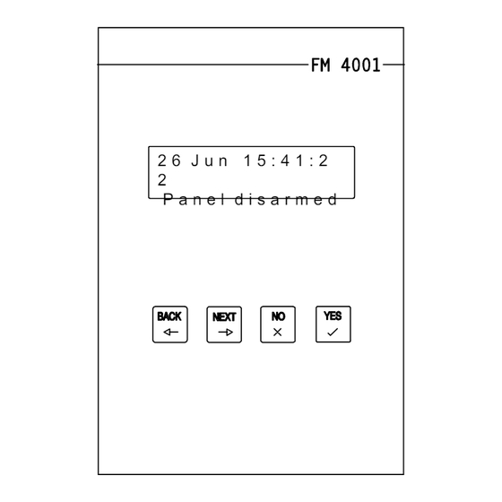
2 6 J u n 1 5 : 4 1 : 2
2
P a n e l d i s a r m e d
ZONES
SIGNALLING
LOW
TAMPER
BATTERY
FM Electronics Ltd
Manufacturer of quality wireless products
CI-123 iSS 2
FIRE
PANIC
FULL SET
PART SET
OFF
ALARM
MAINS ON
FM4000X
Advertisement

Subscribe to Our Youtube Channel
Summary of Contents for FM Electronics FM4000X
-
Page 1: Installation Instructions
FM4000X and FM4001 FAULT FINDING GUIDE CONTROL PANEL CUSTOMER HAD AN ALARM Ask them to press the Full set button and tell you INSTALLATION INSTRUCTIONS what indicators are on. The LED's indicate the cause of the alarm and also the setting status at the time. - Page 2 Options 27 to 50 8 - 10 Auto report fail Low battery Jamming Remote engineer reset Fire Panic Antenna tamper module Armed Aux. Wired arming connections S.A.B. connections LCD unit connection diagram FM4000X Connection diagram Fault finding RSSI RESET VOLTMETER CONNECTION...
- Page 3 System Off LED output for remote correctly. hard wired arming. Indicates when Mount the FM4000X directly below the disarmed. LCD unit and plug in the connecting lead. Part Set hard wired arming input. Apply +12v to arm. Remove to unset.
- Page 4 FM4001 for the installation records. situations where a battery is required in addition to the one already in the FM4000x 4. Locate the control panel For best radio coverage the control panel is best located at a central point in the LINE FAULT OUTPUT TO FM4000X building.
- Page 5 Displays the software issue of the 4000X INSTALLATION cont... panel, press full set to exit. 9. Radio test using the RSSI output Mains supply to the control panel must be To measure the signal strength received 4005 ANTENNA TAMPER MODULE REMOTE ENGINEER provided by a competent electrician to the...
- Page 6 1=2s 2=5s 3=10s 4=15s 5=20s 6=30s the information will not be lost even when The output from the receiver can be heard 7=1min 8=infinite program step. power is removed from the panel. on the panel loudspeaker. This applies to remote control and remote Press the full set key to exit.
- Page 7 entry time when unsetting from Full Set. DETECTOR (If a mains relay was connected via this output a mains courtesy light could be programming). PROGRAMMING cont... 38 NO EXTERNAL BELL OR DIALLER IN switched on by disarming from outside Up to 8 Fire detectors can be programmed PART SET To delete the device press PART SET and with a remote control.)
- Page 8 -ve removed in alarm The factory default is all zones allowed to 28 DOUBLE BUTTON P.A. The 0 key deletes all. be omitted except zone 1. (To activate a panic from a remote control, Press the full set key to exit. The zone LED's indicate which zones are both PA &...
- Page 9 IMPORTANT NOTE IMPORTANT NOTE Programming detectors is different to the standard FM4000. Programming detectors is different to the standard FM4000. e.g. Key in 012 to select device 2 on zone 1. e.g. Key in 012 to select device 2 on zone 1. The LED's will indicate which devices are already programmed on The LED's will indicate which devices are already programmed on that zone &...
Need help?
Do you have a question about the FM4000X and is the answer not in the manual?
Questions and answers