
Subscribe to Our Youtube Channel
Summary of Contents for EarthLinked SCWD-024-1C
- Page 1 Classic Series SCWD Geothermal Heating and Cooling System Quick-Start Instructions SCWD-QS (12/16) ©2016 EarthLinked Technologies, Inc.
- Page 2 Table of Contents List of Figures............................. 3 List of Revisions ..........................4 Model Nomenclature .......................... 5 Safety ..............................6 Equipment Manuals..........................6 Installation ............................7 Component Matching ......................7 Compressor Unit Placement ....................8 Refrigeration ........................9 System Applications and Electrical ..................13 SureStart ...........................
- Page 3 List of Figures Figure 1. Matching Component Model Numbers .................. 7 Figure 2. General Layout of System Components ................8 Figure 3. Compressor Unit Clearance ....................9 Figure 4. SCWD Connections ......................10 Figure 5. Line Set Sizes ........................12 Figure 6.
- Page 4 Figure 33. Compressor Motor Circuit Testing..................51 Figure 34. Compressor Motor Grounded Winding Test ..............52 Figure 35. System Troubleshooting Chart ..................53 Figure A1. SCWD Compressor Unit Electrical Schematic Diagram (No SureStart), 230-1-60……..60 Figure A2. SCWD Compressor Unit Electrical Schematic Diagram (No SureStart), 230-3-60……..61 List of Revisions New EPS system –...
-
Page 5: Model Nomenclature
Earthlinked Technologies. Installation and service must be made in accordance with the instructions set forth in this manual. Failure to provide installation and service by an ETI trained and authorized installer consistent with this manual will void and nullify the limited warranty coverage for the system. -
Page 6: Safety
Equipment Manuals The following is a listing of the equipment installation manuals that are provided with each component ® specified for this EarthLinked system. IMPORTANT! Read and follow all installation instructions in these manuals, ®... -
Page 7: Installation
Installation 1) Component Matching Upon receipt of the equipment, carefully check the component model numbers by referencing Figure 1, to ensure that all components of the system match. Classic Systems Compressor Unit Hybrid Cooling Module Earth Loop -024 -024-C -030 -030-C -036 -036-C... -
Page 8: Compressor Unit Placement
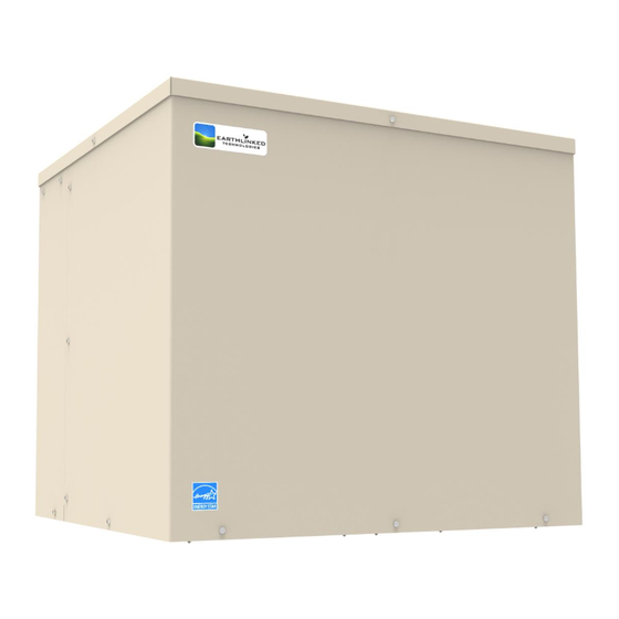
Figure 2. General Layout of System Components 2) Compressor Unit Placement ® EarthLinked SCWD compressor units may be located inside only. When placing it inside, place it on a level, hard surface. Avoid placing the compressor unit in or near sound sensitive areas of the residence. -
Page 9: Refrigeration
Figure 3. Compressor Unit Clearance ® Placement instructions for other pieces of equipment that make up the EarthLinked System are included with those pieces of equipment and are listed in this manual under Equipment Manuals. 3) Refrigeration ® After the EarthLinked compressor unit and other system components are placed, the refrigeration system tubing is run from the compressor unit to the other components, as appropriate. -
Page 10: Figure 4. Scwd Connections
SIZE, INCHES TYPE OF PORT FUNCTION CONNECTION -024 -030 -036 -042 -048 -060 1-1/4” Hole Electrical, Power 7/8” Hole Electrical, Control Plugged ---- ---- ---- ---- ---- ---- ---- Plugged ---- ---- ---- ---- ---- ---- ---- EL Liquid* Braze Anode Socket ---- ----... - Page 11 Compressor units are shipped from the factory with a low pressure nitrogen holding charge. Carefully relieve the holding charge when the compressor unit is being prepared to connect refrigerant system piping. Caution! This compressor unit is equipped with Copeland Ultra 32-3MAF Polyol Ester Oil (POE).
-
Page 12: Figure 5. Line Set Sizes
The compressor unit package contains a service valve kit and an adapter kit. The two service valves are to be installed on the earth loop vapor and liquid connections of the compressor unit, using the adapters to right-size to the proper earth loop line set. Installation of the service valves will provide isolation of the earth loop system from the compressor unit and provide easy access to the refrigerant system. -
Page 13: System Applications And Electrical
4) System Applications and Electrical The SCWD compressor unit electrical box major components and electric data for all compressor sizes are shown in Figure 6. The SureStart Module is an optional factory installed component that (1) reduces compressor starting current, (2) reduces compressor starting torque, thus reducing stress on the compressor at start-up, and (3) monitors the run capacitor. -
Page 14: Figure 6. Scwd Electric Box Components & Electrical Data
Voltage Compressor Compressor Voltage/Phase/ Unit Model Model Min. Max. -024-1C ZP25K6E-PFV 230-1-60 72.5 15.0 18.0 -024-2C ZP25K6E-TF5 230-3-60 61.4 12.0 -030-1C ZP31K5E-PFV 230-1-60 78.0 18.6 23.0 -030-2C ZP31K5E-TF5 230-3-60 73.0 11.6 14.0 -036-1C ZP38K5E-PFV 230-1-60 109.0 22.1 27.0 -036-2C ZP38K5E-TP5 230-3-60 83.1 15.1... -
Page 15: Figure 7. Scwd Compressor Unit Electrical Schematic Diagram, 230-1-60
Figure 7. SCWD Compressor Unit Electrical Schematic Diagram, 230-1-60 SCWD-QS (12/16) Page 15... -
Page 16: Figure 8. Scwd Compressor Unit Electrical Schematic Diagram, 230-3-60
Figure 8. SCWD Compressor Unit Electrical Schematic Diagram, 230-3-60 SCWD-QS (12/16) Page 16... -
Page 17: Figure 9. Scwd Hydronic Heating/Cooling/Water Heating Sytem Application
Figure 9. SCWD Hydronic Heating/Cooling/Water Heating Sytem Application SCWD-QS (12/16) Page 17... -
Page 18: Figure 10. Scwd Hydronic Heating/Cooling/Water Heating System Field Wiring Diagram
Figure 10. SCWD Hydronic Heating/Cooling/Water Heating System Field Wiring Diagram SCWD-QS (12/16) Page 18... -
Page 19: Surestart
5) SureStart Features SureStart is an optional factory installed soft starter that reduces light flicker caused at start-up by scroll compressor motors. This control has the following features: 60 to 70% reduction in direct in-rush current Under voltage protection ... -
Page 20: Figure 11. Surestart Mode Of Operation
Figure 11. SureStart Mode of Operation SCWD-QS (12/16) Page 20... - Page 21 Flash Codes – Single Phase LED Flash Codes A Red LED indicator will flash under the following conditions. [NOTE: LED fault indicator is turned off in normal running mode.] a) Rapid Flash (10 / sec) : Low Voltage b) Triple Flash Every Three Seconds (3 / 3 secs): Lockout on Three Failed Starts c) Slow Flash (1 / 3 secs): Lockout on Over Current d) Slow Steady Flash (1 / sec): Cycle Delay / Fault Mode Flash Code (Rapid Flash (10 / sec) : Low Voltage)
- Page 22 Flash Codes – Three Phase A Red LED indicator will flash under the following conditions. [NOTE: LED fault indicator is turned off in normal running mode.] a) Reverse Phase: (1 / 2 secs) b) Fault Mode/Cycle Delay: (1 / 4 secs) c) Low Voltage/Over Voltage: 2 / 2 secs) Flash Code (Reverse Phase: (1 / 2 secs)) Displayed if the supply “Phase Sequence”...
-
Page 23: Plumbing
6) Plumbing A typical primary hydronic plumbing circuit for an SCWD system is illustrated in Figure 12. Figure 12a. Typical SCWD Primary Hydronic Circuit Plumbing SCWD-QS (12/16) Page 23... - Page 24 5. Hydronic Buffer Tank: The GSTE Series Hydronic Buffer Tanks are available from ETI in 60, ® 80 and 119 US Gallon capacities, and are designed for use with the EarthLinked geothermal systems. They are equipped with a 4.5 kW supplemental heater which satisfies the ETI requirement for a minimum of 20% supplemental heat.
-
Page 25: Antifreeze Protection
SOLUTION PROTECTION IN EARTHLINKED RADIANT PANEL HYDRONIC HEATING AND/OR COOLING SYSTEMS AT THE TIME OF ® SYSTEM START-UP WILL VOID THE EARTHLINKED LIMITED WARRANTY FOR HEATING AND COOLING SYSTEMS. Propylene-glycol antifreeze solution with an inhibitor is the type of antifreeze solution required for ®... - Page 26 The manufacturer’s specific instructions and industry standards always take precedence when introducing propylene-glycol to the system. Calculate the quantity of inhibited propylene-glycol (fluid) required to achieve the desired results. Introduce a sufficient quantity of water to the system and pressure check to ensure a sealed system.
-
Page 27: Internal Heat Recovery System
8) Internal Heat Recovery System The SCWD compressor unit has a built-in heat recovery system which provides supplemental domestic water heating at a significant operating cost savings. The heat recovery system operates throughout the year to provide free hot water when operating in cooling mode and reduced cost hot water when operating in the heating mode. -
Page 28: Figure 12C. Gste Storage Water Heater—Service Connections
Figure 12c. GSTE Storage Water Heater—Service Connections Figure 12d. GSTE Storage Water Heater—Tank Top View SCWD-QS (12/16) Page 28... - Page 29 The SCWD compressor unit Internal Heat Recovery System contains a water high temperature control. It is factory set to 140°F. The Heat Recovery System also contains a refrigerant low temperature which is factory set at 130°F. Also, a freeze protection control is designed to operate the circulating pump when water temperature drops to 40°F, in order to provide water circulation independent of compressor operation.
-
Page 30: Earth Loop Protection System
WARNING! ® All power of the EarthLinked System is to be shut OFF at the disconnect while field wiring the Earth Loop Protection System. Failure to do so may result in serious injury or death, or equipment or property damage. -
Page 31: Figure 14. Disassembled Plug Connector
Figure 14. Disassembled Plug Connector SCWD-QS (12/16) Page 31... -
Page 32: Figure 15. Anode Wire Insertion
Strip the insulation from the multi-strand anode wire back approximately ¾ inch from the end and while keeping the strands together, push the anode wire through the gland nut, gland cage, gland and plug body as shown in Figure 15. Loosen one of the two screw terminals on the plug insert to receive all of the strands of anode wire on one terminal. -
Page 33: Figure 16. Install The Plug Insert
Figure 16. Install the Plug Insert Slide the gland forward on the anode wire until it is firmly seated in the plug body as shown in Figure 17. Next, slide the gland cage over the gland, and slide the gland nut firmly against the gland cage, with the gland nut against the plug body. -
Page 34: Figure 18. Secure The Anode Wire
Once the gland nut has been hand tightened into the plug body, use two adjustable wrenches to further tighten the gland nut until it is snug in the plug body as shown in Figure 18 and the anode wire is held firmly in the plug body and will not slip out. Do not over-tighten the gland nut! Figure 18. -
Page 35: Eps Operation And Service
2) EPS Operation and Service Reference Figure 20 for the EPS components in the compressor unit electric box. Figure 20. Electric Box with EPS Components With power ON, and viewing the EPS Module in the compressor unit electric box, the EPS green light should be illuminated, indicating there is power to the EPS system. -
Page 36: Voltage Verification
IMPORTANT! DO NOT troubleshoot the EPS board! If the above steps do not resolve the problem, call ETI for technical service assistance at 1-863-701-0096. 3) Voltage Verification If it is necessary to verify the voltage output of the EPS system, it can be checked with a digital DC voltmeter. -
Page 37: Start-Up Process
CAUTION! During the Evacuation and Initial Charging processes, be sure that ALL ® power to the EarthLinked System is OFF. This includes the compressor unit, air handler and all other electrically powered system components. Failure to do so will cause lockout on start-up. -
Page 38: Figure 23. Scwd Internal Flow Schematic
Figure 23. SCWD Internal Flow Schematic SCWD-QS (12/16) Page 38... -
Page 39: Figure 24. Scwd Piping
Figure 24. SCWD Piping SCWD-QS (12/16) Page 39... -
Page 40: Evacuation
2) Evacuation Refer to Figure 25 and the following procedure: 1. Carefully vent any pressurized nitrogen charge from the compressor unit and system. 2. After venting the pressurized system, use a good quality gauge manifold and a non-permeable hose set as shown in Figure 25. If possible, use two Schrader core removal tools. Install one on the discharge line access port and the other on the initial charging port. -
Page 41: Figure 25. Evacuation Of Scwd System
Figure 25. Evacuation of SCWD System SCWD-QS (12/16) Page 41... -
Page 42: Initial Charge
3) Initial Charge 1. Disconnect the vacuum pump and isolate the digital vacuum gauge. Connect the refrigerant container to the charging hose of the manifold gauge set as shown in Figure 26. WARNING! Inhalation of high concentrations of refrigerant gas vapor is harmful and may cause heart irregularities or death. -
Page 43: Figure 26. Initial Charge Of Scwd System
Figure 26. Initial Charge of SCWD System SCWD-QS (12/16) Page 43... -
Page 44: Final Charge
4) Final Charge 1. Remove the Schrader core tool from the hose just taken off of the initial charging port. 2. Crack open the LP valve on the manifold gauge set so that a small amount of refrigerant gas flows to purge the hose. Connect the hose to the final charging port, shown in Figure 27. Tighten the hose to the final charging port and turn off the LP valve when the hose connection is secure. -
Page 45: Figure 27. Final Charge Of Scwd System
Figure 27. Final Charge of SCWD System SCWD-QS (12/16) Page 45... -
Page 46: Figure 28. Charging To The Middle Sight Glass (Heat Only Units)
Figure 28. Charging to the Middle Sight Glass (Heat only units) Figure 29. Final charging to the Top Sight Glass (Heat/Cool units) SCWD-QS (12/16) Page 46... -
Page 47: Figure 30. Pressure-Temperature For R-410A
TEMPERATURE (°F) PRESSURE (psig) 26.1 30.8 35.9 41.5 47.5 54.1 61.2 68.8 77.1 86.0 95.5 105.7 116.6 128.3 140.8 154.1 168.2 183.2 199.2 216.1 234.0 253.0 273.0 294.1 316.4 339.9 364.6 390.5 417.7 446.3 476.3 507.6 540.5 574.8 610.6 Figure 30. Pressure-Temperature for R-410A SCWD-QS (12/16) Page 47... -
Page 48: Figure 31. Start-Up Process
Figure 31. Start-Up Process SCWD-QS (12/16) Page 48... -
Page 49: Troubleshooting
AND OR FAIL, 2) PROPERTY DAMAGE, INJURY OR DEATH. IMPORTANT! EarthLinked® Refrigerant System Safety Switches EarthLinked® compressor units are equipped with the following three safety switches that will turn the compressor off if the following limits are exceeded. High Pressure Switch: Located between the compressor discharge port and the reversing valve, the cut-out pressure is 600 psig. -
Page 50: Figure 32. Compressor Unit Voltage Information
Figure 32. Compressor Unit Voltage Information The following compressor checklist is provided to analyze the compressor and determine if it is operating properly or if it is faulty: 1. Electrical Service Panel – turn power off. a. Check circuit terminal connections for tightness b. -
Page 51: Figure 33. Compressor Motor Circuit Testing
Note: Cautiously and carefully feel the top of the compressor to see if it has overheated. If it is hot, the internal overload may be open. You may have to wait several hours for it to reset before proceeding. If the compressor draws a high amperage and does not start (amperage is approximately locked rotor amperage –... -
Page 52: Figure 34. Compressor Motor Grounded Winding Test
8. Grounded Windings Test the compressor motor for a grounded winding. The check should be made using an ohmmeter capable of measuring very high resistance on a VOM. The resistance between windings and the housing is one million to three million ohms for an ungrounded winding. -
Page 53: System
2) System Problem / Likely Cause(s) Action/Correction Symptom 1. Thermostat fault. 1. Adjust thermostat settings. / Replace thermostat. A. System does 2. Power supply problem (AHU / 2. Check power supply for adequate phase and not run. compressor unit). voltage. Check wiring to system and external breakers or fuses. - Page 54 3. Check wiring in system. See appropriate C. System blows fuses or 3. Internal short circuit. Loose or wiring schematics and diagrams. Test trips circuit breaker improper connection in system. components, especially the compressor, (cont.) for shorts and grounds. 4. Excessively high or low supply 4.
- Page 55 5. To reset switch, turn primary power off then back on; G. Uncomfortable 5. Compressor fault. turn thermostat system switch to OFF, then back on. temperature. (Not enough 6. Outdoor thermostat not 6. Check outdoor thermostat and electric supplemental heat/cold air) connected or failed heat operation.
-
Page 56: Commissioning Document
IMPORTANT! ® All EarthLinked system should be commissioned and their location recorded. The selected earth loop configuration must be clearly documented with regard to size, configuration, and detailed location. -
Page 57: Tools And Equipment
Tools and Equipment The purpose of the following list is to highlight key pieces of equipment, tools and materials necessary ® for the installation, maintenance and servicing of EarthLinked Heating and Cooling System HVAC (above ground) equipment. The professional HVAC technician is expected to have a compliment of standard tools for the general servicing of refrigeration equipment. -
Page 58: Triple Evacuation
1. Attach an electronic micron gauge to the system. The best place is as far from the vacuum ® port as possible, which would be the access port on a service valve on the EarthLinked compressor unit. 2. Let the vacuum pump run until the digital vacuum gauge reaches 1500 microns. After reaching 1500 microns, isolate the digital vacuum gauge. -
Page 59: Appendix A: Electrical Diagrams – No Surestart
Appendix A: Electrical Diagrams – No SureStart The following compressor unit electrical diagrams do not include SureStart. They are as follows: Figure A1. SCWD Compressor Unit Electrical Schematic Diagram (No SureStart), 230-1-60……..60 Figure A2. SCWD Compressor Unit Electrical Schematic Diagram (No SureStart), 230-3-60……..61 SCWD-QS (12/16) Page 59... -
Page 60: Figure A1. Scwd Compressor Unit Electrical Schematic Diagram (No Surestart), 230-1-60
Figure A1: SCWD Compressor Unit Electrical Schematic Diagram (No SureStart), 230-1-60 SCWD-QS (12/16) Page 60... -
Page 61: Figure A2. Scwd Compressor Unit Electrical Schematic Diagram (No Surestart), 230-3-60
Figure A2: SCWD Compressor Unit Electrical Schematic Diagram (No SureStart), 230-3-60 SCWD-QS (12/16) Page 61... -
Page 62: Appendix B: Functions Of The Nano-Plc
Appendix B: Functions of the Nano-PLC Programmable Logic Controllers (Nano-PLC) come standard in all Prime Series units as well as in the Classic SDH, SCW and SCWD. The Nano-PLC is programmed to ensure different functions depending on the units; you can find a detailed description of these functions below. Functions of SCW and SCWD systems equipped with the Nano-PLC (Hydronic Heat/Cool): SCW and SCWD units keep the same functions as always for installation and use.
Need help?
Do you have a question about the SCWD-024-1C and is the answer not in the manual?
Questions and answers