Table of Contents
Advertisement
Installation and Operating Instructions
Premier Series
24 Volt
PFC-A24
PFC-A24-RS
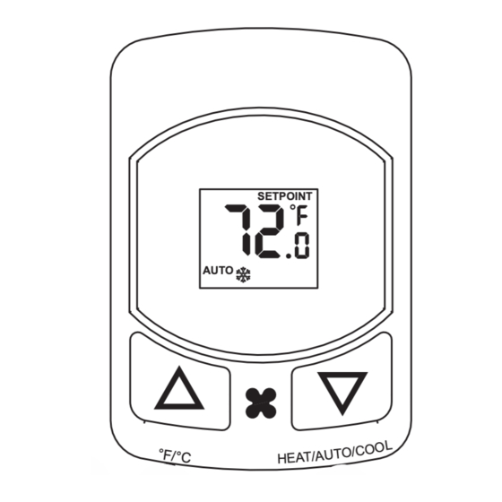
AUTO
Increase
temperature
Switches between
°F and °C
Application:
This thermostat is a 24 volt heating and cooling digital temperature
control designed to operate 2 or 4-pipe fan coil systems. Switching
of load circuits is through relay contacts. Fan outputs can be
configured to operate 3, 2 or single speed fan motors. The fan control
also has configurations for user select fan speed with economy
function, continuous fan or auto cycle fan. This thermostat operates
on a single setpoint with automatic changeover from heating to cooling.
Installation Notice:
This high performance digital thermostat is designed to provide many
years of superior comfort control when properly installed and maintained.
To achieve maximum performance, this device is designed to draw
room air into itself continuously. Reasonable care must therefore be
taken with regard to air quality at the time of installation as well as
during periods of normal use, see operating conditions below.
Operating Conditions:
The electronic mechanisms incorporated within this unit REQUIRE
operating conditions similar to other electronic devices intended for
INDOOR USE ONLY, such as would be acceptable for TV and similar
household appliances. Relative humidity must be less than 95% and
the atmosphere must be non-condensing. For operation in bathrooms,
shower or pool areas, outdoor entry ways, greenhouses and similar
applications, order the "-k" option. This product includes protection
for coastal/tropical application, therefore it is suitable for use in high
humidity environments. Air quality must be maintained FREE of heavy
dust or debris which may infiltrate the interior of this device. Installation
in any space which is unfinished or undergoing repainting or general
rehabilitation is also considered product abuse. This device should be
removed from service during any local construction activity.
Cleaning:
This device incorporates a high impact polycarbonate enclosure which
is easily cleaned with a dry cloth or vacuum brush. Occasional soiling
may be cleaned with a soft cloth lightly dampened with water and/or
mild cleaning solution. IN NO CASE should this device be directly
sprayed with or exposed to free flowing liquids, including water, which
could penetrate its interior.
FAILURE TO OBSERVE ANY OF THE ABOVE CONDITIONS OF USE
WILL COMPLETELY VOID THE SUPPLIER WARRANTY.
MAKE SURE UNIT IS PROPERLY CONNECTED. DAMAGE TO THE
DIGITAL CONTROL CAN BE CAUSED BY MISWIRING, WHICH WILL
VOID THE WARRANTY. FOR SAFETY REASONS ALWAYS USE
WIRE NUTS ON ALL WIRE CONNECTIONS!!!
PFC-M24
PFC-M24-RS
SETPOINT
◦ ◦
AUTO
Decrease
temperature
Selects
System Mode
fan
Switch
function
CAUTION
Specifications:
Temperature Monitor Range: 32.2°F to 99.9°F (0.0°C to 37.7°C)
Setpoint Range: 60.0°F to 85.0°F (15.5°C to 29.5°C)
*Setpoint: 72°F (22°C)
*Comfort Limits: 65.0°F (18.5°C) cooling
Display Format: Liquid Crystal Display (LCD)
Backlight: EL blue green
Sampling Rate: Every 15 seconds
SETPOINT
◦ ◦
Accuracy: ± 1°F (0.5°C)
Power Source: 24VAC/DC (20 minimum to 32 maximum)
Load Rating: 1.5 amps per load circuit
*Fan Control: Selectable: Auto cycle, Low, Medium, High
Heat/Cool Control: 1 heat and 1 cool circuit (see system function)
*Economy Limits:
Maintains room temperature between 60.0°F and 85.0°F
(15.5°C and 29.5°C) when thermostat is in economy (ECON) mode
*Fan Purge Timer: 30 seconds
Anti-short Cycle: 3 minute hold in no call state at all times
*Cycle Rate: 8 cycles per hour
* Differential: 0.4°F
* Display Mode: Setpoint temperature
* System Function: Heat and Cool
*See Field Programming Instructions
This device should be installed and serviced by a qualified technician.
Junction box mounting is highly recommended.
1.
Caution: Make sure that power has been disconnected.
2. All wiring must comply with applicable codes and ordinances.
3. A thorough check-out of the system should be made after
installation is complete.
4. If fan motor is larger than 1/4 HP and/or electric heaters are used
for heating, additional power relays will be required
5. If retrofitting old thermostat, remove old thermostat from the
junction box, carefully noting the wire connections on the old unit.
Record wire color and terminal legends in spaces provided.
Disconnect old thermostat and remove any existing backplate or
mounting plate.
6. Install the mounting bracket to the
junction box with the two long
mounting screws provided.
See mounting detail to the right.
Note: If application involves a
double ganged junction box,
a backplate will be required for a
complete installation.
Please consult your supplier.
User Note: The top of this unit will become warm to the touch. This is a
normal operation. Internal heating is employed to continuously convect
air upward through the thermostat, thereby improving room air temperature
measurement. Direct conflict with a downward ceiling fan or system fan air
flow may result in false temperature reading. Locate thermostat to avoid
interference.
1
85.0°F (29.5°C) heating
4-PIPE FAN COIL, 2-PIPE ELECTRIC HEAT OR
ELECTRONIC AQUASTAT INSTALLATION:
Old thermostat
wire function
Power Feed
Common
Heat
Cool
Low Fan
Medium Fan
High Fan
Screw: 6/32 x 3/4"
Cable
wire color
Mounting Bracket
Standard
Junction
Box
Advertisement
Table of Contents
Troubleshooting

Related Manuals for PSG PFC-M24


Summary of Contents for PSG PFC-M24
- Page 1 Installation and Operating Instructions Specifications: Premier Series Temperature Monitor Range: 32.2°F to 99.9°F (0.0°C to 37.7°C) PFC-M24 Setpoint Range: 60.0°F to 85.0°F (15.5°C to 29.5°C) 24 Volt PFC-M24-RS *Setpoint: 72°F (22°C) *Comfort Limits: 65.0°F (18.5°C) cooling 85.0°F (29.5°C) heating Display Format: Liquid Crystal Display (LCD)
- Page 2 7. From the wire chart found in step 5, assign, according to function, BASIC FUNCTIONS Setpoint the cable wire colors to the thermostat wire legend provided below. Indicator Note: The control feed and the load feed will be connected together Room for the 4-pipe installation.
- Page 3 2-PIPE FAN COIL INSTALLATION: (Bimetal Aquastat ONLY) Check Cooling: NOTE: For Electronic Aquastat applications (RS models) use the Press and hold the down button until the cool SETPOINT 4-Pipe wiring ONLY. symbol appears on the LCD. Within 4 seconds Follow the instructions for a 4-pipe installation with the following AUTO the cool valve will be activated.
- Page 4 FUNCTION CHART TROUBLE SHOOTING TESTS (2-Pipe System) Heating Season, Hot Pipe Voltage: When using a voltmeter across “Black" and "Red", voltage SYSTEM FAN SPEED Adjust setpoint as follows: must be 24VAC. HEAT COOL AUTO HIGH To Check Continuity: (Using a Voltmeter with all loads connected) 6.0°F or more ABOVE room temperature 3.0°F to 5.9°F ABOVE room temperature Cold pipe or season switch set to cool: (power supplied through...
- Page 5 PFC-ALV-RS and PFC-MLV-RS models ONLY function. SEN2 is to be used only as a room temperature sensor (order PSG P-RS). SEN3 is to be used only with the Electronic Aquastat Kit (order PSG P-AK). The REF terminal is common to both sensor inputs.
- Page 6 Any PSG product that proves defective within the above described warranty period will be repaired or replaced (at PSG's option) free of any charge if returned to the PSG factory at 1225 Tunnel Road, Perkasie, PA. 18944 with transportation charges...
Need help?
Do you have a question about the PFC-M24 and is the answer not in the manual?
Questions and answers