
Related Manuals for SCHOTT CG 853P


Summary of Contents for SCHOTT CG 853P
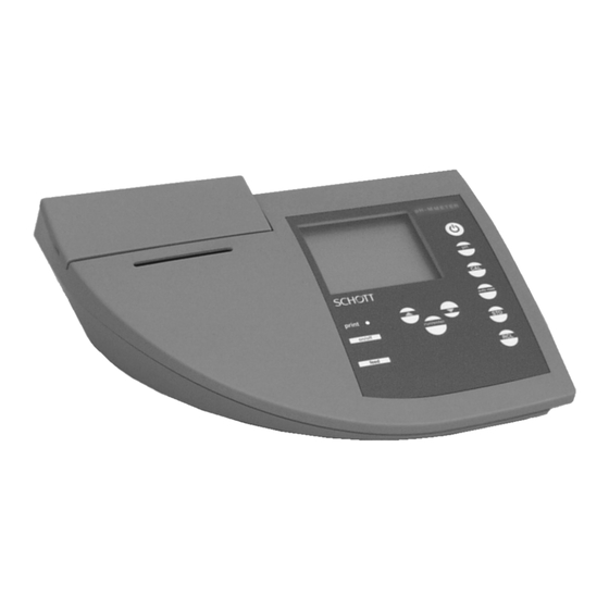
- Page 1 Operating Manual Laboratory conductivity meter CG 853P Conductivity meter with integrated printer ba12246e_2 09/99...
- Page 2 All details contained in this operating manual are valid data going to press at the time of going to press. However, SCHOTT may add details for both technical and commercial reasons, or in or- der to fulfil legal requirements of different countries. This does not affect the characteristics described.
- Page 3 List of contents Overview ....... . 81 1.1 Keyboard ....... .82 1.2 Display .
- Page 4 List of contents Maintenance, cleaning, disposal ... 139 5.1 Maintenance ......139 5.1.1 Changing the batteries .
-
Page 5: Overview
The compact CG 853P precision conductivity meter lets you perform conductivity measurements rapidly and reliably. The CG 853P provides the highest degree of operating com- fort, reliability and measuring safety for all applications. The integrated printer enables the measurements to be documented in compliance with GLP. -
Page 6: Keyboard
Overview Keyboard Measuring instrument ON/OFF <on/off> Select measuring mode ì < > Set up or determine cell constant; select temperature compensation <CAL> Activate/deactivate AutoRead function <auto read> Store measured value <STO> Display/transmit measured values <RCL> Reduce values, scroll < > Confirm inputs, start AutoRead <run/enter>... - Page 7 Overview Print LED Red: printer off (offline) or malfunction Green: printer ready for operation (online) Printer ON/OFF <print on/off> Paper feed/line feed (Printer off - Print LED lights up red) <feed>...
-
Page 8: Display
RS 232 interface/analog output Plug-in power supply Caution Only connect probes to the instrument that cannot feed excessive voltages or currents (> SELV and > circuit with current limiter). Almost all commercial electrodes - especially SCHOTT electrodes - meet these requirements. -
Page 9: Declaration Of Conformity
Overview Declaration of Conformity 29.03.99 SCHOTT Geräte GmbH Im Langgewann 5 D 65719 Hofheim am Taunus Deutschland, Germany, Allemagne 29. März, March 29rd, 29, Mars, 1999 AGQSF0000-A060-00/990329... -
Page 10: Technical Data
Overview Technical data Ambient Storage tempera- - 25 °C ... + 65 °C temperature ture Operating temper- 0 °C ... + 55 °C ature Allowable relative Annual mean: < 75 % humidity 30 days/year: 95 % Other days: 85 % [µS/cm] 0.000 ... - Page 11 ± 0.5 %0 °C ... 35 °C according to EN 27 888; ± 0.5 % 35 °C ... 50 °C extended nLF function according to SCHOTT measurements Linear compensation AccuracyTest sample temperature ± 0.5 % 10 °C ... 75 °C...
- Page 12 Overview Measuring accuracy T [°F] NTC 30: (± 1 digit) Accuracy± 0.2 (Continuation) PT 1000: AccuracyOperating temperature ± 0.9 at 32 °F ... 59 °F ± 0.2at 59 °F ... 95 °F ± 1.8 at 95 °F ... 131 °F Cell constant, C [cm 0.01...
- Page 13 Overview Power supply Batteries 4 x 1.5 V AA type alkaline manga- nese batteries Runtime Approx. 3000 operating hours Mains power supply Connection max. overvoltage cat- egory II: Plug-in power supply (Euro plug): Type no.: Z851 Order no.: 28 520 4897 FRIWO FW3288, 11.8134 Friwo Part No.
- Page 14 Overview Test marks TÜV GS, UL/CUL, CE Display Multifunctional LCD Keypad Foil keypad (Polyester) Data storage Ring store for 200 value pairs, conductivity/salinity/TDS, temperature Automatic with Pt -5 ... 100.0 °C Temperature 1000/NTC (30 k compensation Manual input -5 ... 100 °C resolution 1K Measuring cell 8 pole socket with pin contacts Connectors...
-
Page 15: Safety
Safety Safety This operating manual contains basic instructions that you must follow during the commissioning, operation and main- tenance of the instrument. Consequently, all responsible personnel must read this operating manual before working with the instrument. The operating manual must always be available within the vicinity of the instrument. -
Page 16: Authorized Use
In this event, wait until the temperature of the instrument reaches room tem- perature before putting the instrument back into operation. Caution The instrument is only allowed to be opened by personnel authorized by SCHOTT. - Page 17 Safety Safe operation If safe operation is no longer possible, the instrument must be taken out of service and secured against inadvertent operation. Safe operation is no longer possible if: the instrument has been damaged in transport the instrument has been stored under adverse conditions for a lengthy period of time the instrument is visibly damaged the instrument no longer operates as described in this...
- Page 18 Safety...
-
Page 19: Commissioning
Commissioning Commissioning Perform the following activities for initial comissioning: Set the date and time Connect the plug-in power supply (for printer functions). ì Setting the date 1 Press and hold down the < > key. and time 2 Press the <on/off> key. The display test appears briefly on the display. - Page 20 ECHNICAL DATA 1 Insert the plug (1) into the socket (2) of the conductiv- ity meter. 2 Connect the original SCHOTT plug-in power supply (3) to an easily accessible mains socket. Note You can also perform measurements without a plug-in power supply.
-
Page 21: Operation
Operation Operation Switch on the instrument 1 Place the instrument on a flat surface and protect it against intense light and heat. 2 Connect the conductivity measuring cell to the instru- ment. 3 Press the <on/off> key. The display test appears briefly on the display. The instrument then switches automatically to the previously selected measuring mode. - Page 22 Operation Checking the cell 1 Press the <CAL> key repeatedly until LF CELL is dis- constant played. 2 Press the <run/enter> key. The previously selected cell constant ist displayed, e. g. 0.475 cm with a calibrated cell constant. ì 3 To return to the measuring mode: press the < >...
-
Page 23: Measuring
Measurements can be performed with and without a temper- ature probe. A connected temperature probe is indicated by TP on the display. If you want to use a SCHOTT conductivity measuring cell without a temperature probe, you have to connect it with an adapter (available at SCHOTT). - Page 24 Operation AutoRead AR The AutoRead function (drift control) checks the stability of (Drift control) the measurement signal. The stability has a considerable effect on the reproducibility of the measured value. ì Call up the measuring mode by pressing < >. 2 Activate the AutoRead function by pressing <auto read>.
-
Page 25: Conductivity
Operation 4.2.1 Conductivity To measure the conductivity, proceed as follows: 1 Perform the preparatory activities according to sec- tion 4.2. 2 Immerse the conductivity measuring cell into the test sample. ì 3 Press the < > key until appears in the status dis- play. -
Page 26: Salinity
Operation 4.2.2 Salinity To measure the salinity, proceed as follows: 1 Perform the preparatory activities according to sec- tion 4.2. 2 Immerse the conductivity measuring cell into the test sample. ì 3 Press the < > key repeatedly until Sal appears in the status line. -
Page 27: Tds (Total Dissolved Solids)
Operation 4.2.3 TDS (total dissolved solids) To measure the TDS, proceed as follows: 1 Perform the preparatory activities according to sec- tion 4.2. 2 Immerse the conductivity measuring cell into the test sample. 3 When measuring with an integrated temperature probe continue with step 4. - Page 28 Operation 7 Perform an AutoRead measurement according to section 4.2.
-
Page 29: Printing/Transmitting Measured Values
Operation 4.2.4 Printing/transmitting measured values Measured values (data records) can be: printed on the integrated printer or transmitted to the interface. Note To print, you must switch on the printer using the Print key <print on/off> (Print LED lights up green). To transmit to the interface, you must connect the interface cable. -
Page 30: Determining/Setting Up The Cell Constant [C]
Operation Determining/setting up the cell constant [C] Why determine/set Due to ageing, the cell constant slightly changes. As a up the cell result, an inexact measured value is displayed. Calibration constant? determines the current value of the cell constant and stores this value in the instrument. - Page 31 Operation 4 Immerse the measuring cell into the 0.01 mol/l KCL control standard. 5 Press the <run/enter> key. – If no temperature probe is connected, enter the current temperature of the solution using < > < > and confirm with <run/enter> –...
- Page 32 Operation Note This method of automatically determining the cell constant by calibrating in the 0.01 mol/l KCL control standard can only be used for measuring cells with a cell constant in the range 0.450 ... 0.500 cm or 0.800 ... 1.200 cm Calibration After calibrating, the instrument automatically evaluates the evaluation...
- Page 33 Operation Calibration interval The flashing sensor symbol reminds you to calibrate regu- (Int 3) larly. After the selected calibration interval (Int 3) expires, the sensor symbol flashes. Measurements can continue. Note To ensure the high measuring precision of the measuring system, perform a calibration after the calibration interval expires.
- Page 34 Operation Setting up the cell To set up the cell constant manually, proceed as follows: constant manually 1 Press the <CAL> key repeatedly until LF CELL ap- pears on the display. 2 Press the <run/enter> key. 3 Press the <CAL> key repeatedly until the cell con- stant to be set, e.
- Page 35 Operation Note The cell constant to be set up must either be taken from the operating manual of the measuring cell or is printed on the measuring cell. Selecting the To select the 0.1 cm cell constant proceed as follows: 0.1 cm 1 Press the <CAL>...
- Page 36 Operation Selecting the To select the 0.01 cm cell constant proceed as follows: 0.01 cm 1 Press the <CAL> key repeatedly until LF CELL ap- cell constant pears on the display. 2 Press the run/enter> key. 3 Press the <CAL> key repeatedly until the 0.010 cm cell constant appears on the display.
- Page 37 Operation Setting up the The calculation of the temperature compensation is based temperature on the preset reference temperature, Tref 20 or Tref 25 (see compensation TC chapter 4.6 C ONFIGURATION You can select one of the following temperature compensa- tions: Non-linear temperature compensation "nLF"...
- Page 38 Operation Selecting the non- To select the non-linear temperature compensation proceed linear temperature as follows: compensation 1 Press the <CAL> key repeatedly until LF tc appears on the display. 2 Press the <run/enter> key. 3 Press the <CAL> key repeatedly until nLF appears on the display.
- Page 39 Operation Selecting the linear To select the linear temperature compensation proceed as temperature follows: compensation 1 Press the <CAL> key repeatedly until LF tc appears on the display. 2 Press the <run/enter> key. 3 Press the <CAL> key repeatedly until the adjustable linear temperature coefficient appears on the display.
- Page 40 Operation Switching off the To switch off the temperature compensation proceed as fol- temperature lows: compensation 1 Press the <CAL> key repeatedly until LF tc appears on the display. 2 Press the <run/enter> key. 3 Press the <CAL> key repeatedly until the following display appears.
-
Page 41: Storing
Operation Storing The conductivity meter has an internal data storage device. Up to 200 data records can be stored in it. A complete data record consists of: Memory location Date Time Measured value Temperature I.D. number You can transmit measured values (data records) to the data storage in 2 ways: Manual storage Switching on the AutoStore function (Int 1), see page 119... - Page 42 Operation 2 Confirm with <run/enter>. The display changes to the input of the I.D. number. 3 Enter the required I.D. number (1 ... 999) by pressing < > < >. 4 Confirm with <run/enter>. The instrument changes to the measuring mode. *( +,, message This message appears if all 200 memory locations are full.
- Page 43 Operation 4.4.2 Switching on AutoStore (Int 1) The storage interval (Int 1) determines the time interval between automatic storage processes. After the time interval expires, the current data record is transmitted to the data storage and to the interface. The storage interval (Int 1) is set to OFF in the factory. Thus, the AutoStore function is switched off.
- Page 44 Operation 5 As soon as all 200 memory locations are full, the Au- toStore function is terminated (Int 1 = OFF). If too few storage locations are available for your measurements: – backup the data storage (see page 121) and –...
-
Page 45: Outputting The Data Storage
Operation Switching off the Switch off the AutoStore function by: AutoStore Setting the storage interval (Int 1) to OFF or Switch the conductivity meter off and on again. 4.4.3 Outputting the data storage The contents of the data storage can be output to the: display interface Outputting to the... - Page 46 Operation 3 After 2 s the respective temperature of the data record appears on the display. Stored data records are displayed together with the RCL display indica- tor. You can perform the following activities: Display further parameters of the data Press record (I.D.
- Page 47 Operation Note If you want to find a specific parameter (e.g. date), proceed as follows: 1 Press the <RCL> key repeatedly until Sto disp ap- pears on the display. 2 Press the <run/enter> key. A measured value appears on the display. The I.
- Page 48 Operation Outputting to the 1 Press the <RCL> key repeatedly until Sto SEr ap- interface pears on the display. 2 Press the <run/enter> key. The protocol of the last calibration is transmitted to the printer/RS interface. In the meantime, Sto CAL appears on the display.
- Page 49 Operation Sample printout CALIBRATION PROTOCOL 14.04.99 11:37 Device No.: 99990000 CALIBRATION CONDUCTIVITY Cal Time: 14.04.99 / 11:37 Cal Interval: 180d Cal Std.: 0.01 mol/l KCL 23.0 °C Conduct./Tref25: 1413 µS/cm Cell Const : 0.975 1/cm Probe: 01.01.99 00:04 2.40 mS/cm °C Tman Tref25...
- Page 50 Operation Contents of the measuring storage: – Number of the storage location (No.) – Date/time of measurement – Measured value/unit (mS/cm) [°C/F] – Automatic/manual temperature measurement (Tauto/Tman) – Temperature compensation (nLF) – Tref – Cell constant (1/cm) – AutoRead function (AR) –...
-
Page 51: Clearing The Storage
Operation 4.4.4 Clearing the storage This function can erase the stored data records. 200 mem- ory locations will then become available again. Note The Clear store function only appears if data records have already been stored in the storage. Otherwise, the conduc- tivity meter automatically changes to the measuring mode. -
Page 52: Data Transmission
Operation Data transmission You can use the following options to transmit data: One of the following options: – The AutoStore function (page 119) is used to periodically ( Int 1 storage interval) save measured values internally and output them on the interface. –... - Page 53 Operation Setting the The interval is set to OFF in the factory. data transmission To start the data transmission, set up an interval (5 s, 10 s, interval 30 s, 1 min, 5 min, 10 min, 15 min, 30 min, 60 min): 1 Press and hold down the <run/enter>...
-
Page 54: Recorder (Analog Output)
Operation 4.5.2 Recorder (analog output) You can transmit the data to a recorder via the analog out- put. Connect the analog output to the recorder via the Z394 interface cable. The data output switches automatically to recorder output . 1 Free Socket assignment 2 Plug coding 3 Ground... -
Page 55: Pc/External Printer (Rs232 Interface)
Operation 4.5.3 PC/external printer (RS232 interface) You can transmit data to a PC or an external printer via the RS232 interface. Connect the interface to the instrument via the Z395 cable (PC) or Z391 cable (external printer). The data output switches automatically to RS232 . Note The RS232 interface is not galvanically isolated. -
Page 56: Configuration
Operation Configuration You can adapt the conductivity meter to your individual requirements. To do this, the following parameters can be called up/changed (the status on delivery is marked in bold): Baud rate 1200, 2400, 4800. 9600 Data transmission inter- OFF, 5 s, 10 s, 30 s, val (Int 2) 1 min, 5 min, 10 min, 15 min, 30 min, 60 min... - Page 57 Operation Baud rate 4 Set up the required baud rate by pressing < > < >. 5 Confirm with <run/enter>. Int 2 appears on the display. Data transmission interval 6 Set up the required time interval by pressing < > < >. 7 Confirm with <run/enter>.
- Page 58 Operation Calibration interval 8 Set up the required time interval by pressing < > < >. 9 Confirm with <run/enter>. ARng appears on the display. ARng (AutoRange) 10 With < > < > select between YES and no. 11 Confirm with <run/enter>. t25 appears on the display.
- Page 59 Operation Reference temperature 12 With < > < > select between t25 and t20 13 Confirm with <run/enter>. LF appears on the display. Conductivity Ω. 14 With < > < > select between S/cm and M 15 Confirm with <run/enter>. USE °C appears on the display.
- Page 60 Operation Date and time 18 Set today’s date by pressing < > < >. 19 Confirm with <run/enter>. The date (month) flashes on the display. 20 Set the current month by pressing < > < >. 21 Confirm with <run/enter>. The year appears on the display.
-
Page 61: Reset
Operation Reset You can reset (initialize) measuring and configuration parameters separately from one another. Measuring The following measuring parameters (Cond InI) are reset to parameters the values they had on delivery: Measuring mode Cell constant 0.475 cm (calibrated) 0.475 cm (set up) Temperature compensation... - Page 62 Operation Resetting 1 Press and hold down the <run/enter> key. measuring 2 Press the <CAL> key. parameters 3 Use < > < > to toggle between no and yes. yes: reset measuring parameters. no: retain settings. 4 Confirm with <run/enter>. The instrument changes to the configuration para- meters.
- Page 63 Maintenance, cleaning, disposal Maintenance, cleaning, disposal Maintenance The maintenance tasks are restricted to the following activi- ties: replacing the batteries and replacing the roll of printer paper. Note See the relevant operating manual of the electrode for instructions on maintenance.
- Page 64 Maintenance, cleaning, disposal 5.1.1 Changing the batteries 1 Open the battery compartment (1) on the underside of the instrument. 2 Remove the four batteries from the battery compart- ment. 3 Insert four new batteries (Type Mignon AA) into the battery compartment. 4 Close the battery compartment (1).
- Page 65 (3) from underneath. – Press the <feed> Print key (paper feed). 5 Close the lid of the printer (1). Note Only use original SCHOTT HQ thermal paper. Information on this is given in the SCHOTT general catalog.
- Page 66 Maintenance, cleaning, disposal Cleaning Occasionally wipe the outside of the measuring instrument with a damp, lint-free cloth. Disinfect the housing with iso- propanol as required. Caution The housing is made of synthetic material (ABS). Thus, avoid contact with acetone or similar detergents that contain solvents.
- Page 67 What to do if... What to do if... Cause Remedy Error message, – Measuring cell not – Connect measuring connected cell – Cable broken – Replace electrode Cause Remedy Error message, – Measuring cell – Clean measuring cell; contaminated if necessary, replace it –...
- Page 68 What to do if... Integrated printer Cause Remedy does not print – Printer switched off – Switch on printer – No mains power supply – Connect mains power connected supply – Interface cable – Unplug cable connected – No paper available –...
- Page 69 Lists Lists This chapter provides additional information and orientation aids. Abbreviations The list of abbreviations explains abbreviations that appear on the display or when dealing with the instrument. Specialist terms The glossary briefly explains the meaning of the specialist terms. However, terms that should already be familiar to the target group are not described here.
- Page 70 Lists Abkürzungsverzeichnis Conductivity value Plastic housing AutoRead (drift control) ARng Automatic range switching Measuring instrument measures with high- est resolution AutoStore Automatic storing Baud Baud rate Cell constant cm Calibration CELL Cell constant disp Display Output of the data storage on the display Error message (see chapter 6 W HAT TO DO ...)
- Page 71 Lists Sto CIr Clear storage Sto disp Output of the data storage on the display Sto Full Memory full Sto SEr Output of the data storage to the printer/ interface Tauto Automatic temperature measurement Temperature coefficient Total dissolved solids Temperature Probe Temperature measurement active Tref 20/T20 Reference temperature 20 °C...
- Page 72 Lists Glossary AutoRead Monitors the electrode drift and releases the measured value only after the stability criterion has been reached. In this way, this procedure ensures the highest degree of pre- cision and reproducibility. Calibration The cell constant is determined through calibration. To do so, the conductivity measuring cell is immersed into a series of aqueous salt solutions with exactly known electric con- ductiviy.
- Page 73 Lists Resistance All substances (solids, liquids, or gases) with mobile charge carriers like for example electrons or ions have a finite ohmic resistance, which means they have an electric conductance that can be measured or an electric conducitivtiy. Salinity The salinity is a sum parameter especially for seawater; it gives the salt content of seawater.
- Page 74 Lists...
- Page 75 Lists Index analog output 130 initialize 137 authorized use 92 interval AutoRange 134 calibration (Int 3) 109 AutoRead 100 storing (Int 1) 119 AutoStore 119 keys 82 batteries replacing 139 linear temperature compensation 113, battery compartment 140 baud rate, setting 133 LoBat 143 calibration 106 maintenance 139...
- Page 76 Lists recorder output 130 reference temperature 135 replacing the roll of printer paper 141 reset 137 RS232 interface 131 safety 91 safety precautions 91 salinity 130 salinity measurement 102 sockets 84 storing 117 TDS 130 TDS (total dissolved solids) 103 temperature compensation 113 linear 115 non-linear 114...
Need help?
Do you have a question about the CG 853P and is the answer not in the manual?
Questions and answers