
Summary of Contents for Foundry FastIron SuperX
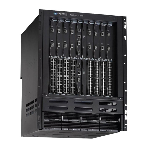
- Page 1 Foundry® FastIron X Series Chassis Hardware Installation Guide FastIron SuperX FastIron SX 800 FastIron SX 1600 FastIron SX 1600-ANR FSX 05.0.00 Release Date: December 16, 2008 Publish Date: December 31, 2008...
- Page 2 The trademarks, logos and service marks ("Marks") displayed herein are the property of Foundry or other third parties. You are not permitted to use these Marks without the prior written consent of Foundry or such appropriate third party. Foundry Networks, BigIron, Terathon, FastIron, IronView, JetCore, NetIron, ServerIron, TurboIron, IronWare, EdgeIron, IronPoint, SecureIron, the Iron family of marks and the Foundry Logo are trademarks or registered trademarks of Foundry Networks, Inc.
- Page 3 EATURES FSX C ............................2-4 HASSIS FSX 800 C ..........................2-5 HASSIS FSX 1600 C ..........................2-7 HASSIS FSX 1600-ANR C ........................2-9 HASSIS ........................2-11 ANAGEMENT ODULES (FSX 800 FSX 1600 ) ...............2-19 WITCH ABRIC ODULES ONLY December 2008 © 2008 Foundry Networks, Inc.
- Page 4 HECKING ONNECTIVITY ......................4-1 SSIGNING ERMANENT ASSWORDS ....................4-2 ECOVERING FROM A ASSWORD IP A ........................4-3 ONFIGURING DDRESSES ............................4-3 EVICES ............................4-4 EVICES .......................4-6 ONNECTING ETWORK EVICES ........................4-6 ABLE PECIFICATIONS .................4-6 ONNECTING TO THERNET OR THERNET © 2008 Foundry Networks, Inc. December 2008...
- Page 5 ITLESS PGRADE AND ITLESS WITCHOVER ......................6-8 AYER ITLESS WITCHOVER OS U ......................6-8 AYER ITLESS PGRADE ..................6-11 ONITORING ANAGEMENT ODULE EDUNDANCY ...................6-11 ETERMINING ANAGEMENT ODULE TATUS ...................6-13 ISPLAYING EMPERATURE NFORMATION .....................6-13 ISPLAYING WITCHOVER NFORMATION December 2008 © 2008 Foundry Networks, Inc.
- Page 6 EPLACING THE SSEMBLIES ................7-33 PGRADING THE EVICE TO AYER OFTWARE HAPTER ............... 8-1 ARDWARE PECIFICATIONS ...........................8-1 HASSIS PECIFICATIONS .........................8-1 HYSICAL IMENSIONS ......................8-2 NVIRONMENTAL ONSIDERATIONS .............................8-2 OOLING ........................8-6 EGULATORY OMPLIANCE ......................8-7 AXIMUM OWER ONSUMPTION © 2008 Foundry Networks, Inc. December 2008...
- Page 7 ................B-1 EGULATORY TATEMENTS U.S.A............................... B-1 ......................... B-1 NDUSTRY ANADA TATEMENT ........................... B-1 UROPE AND USTRALIA ............................... B-1 APAN ..............................B-2 OREA PPENDIX ................C-1 AUTIONS AND ARNINGS ..............................C-1 AUTIONS .............................. C-11 ARNINGS December 2008 © 2008 Foundry Networks, Inc.
- Page 8 FastIron Hardware Installation Guide for the FSX, FSX 800, and FSX 1600 viii © 2008 Foundry Networks, Inc. December 2008...
-
Page 9: C Hapter
Chapter 1 About This Guide Introduction This guide applies to and describes the FastIron SuperX® (FSX), FastIron SX 800® (FSX 800), FastIron SX 1600® (FSX 1600), and FastIron SX 1600-ANR® (FSX 1600-ANR) Layer 2/Layer 3 switches from Foundry Networks. The FSX, FSX 800, FSX 1600, and FSX 1600-ANR are collectively referred to throughout this manual as the FastIron X Series chassis devices. -
Page 10: Rrors
How to Get Help Foundry Networks is committed to ensuring that your investment in our products remains cost-effective. If you need assistance or find errors in the manuals, contact Foundry Networks using one of the following options. Web Access Go to kp.foundrynet.com and log in to the Knowledge Portal (KP) to obtain more information about a product, or to report documentation errors. -
Page 11: Orks
Optional dual management modules on the FSX 800 and FSX 1600 provide 100% redundancy. • The crossbar (xbar) architecture enables the management module to switch 30 Gigabits per second between December 2008 © 2008 Foundry Networks, Inc. 2 - 1... -
Page 12: Device.
800 and FSX 1600 Management Modules” on page 2-15. All FastIron X Series chassis devices optionally support Power over Ethernet (POE), providing the means for integrating data, voice, and video over existing Ethernet cables. 2 - 2 © 2008 Foundry Networks, Inc. December 2008... -
Page 13: Software Features
Software features differ depending on the software version that is loaded on the device and the type of management module that is installed in the chassis. See the Foundry FastIron Configuration Guide for a complete list of software features supported on your device. -
Page 14: M Odules (Fsx
Upon shipment from the factory, the following components are installed in the FSX chassis: • A slot panel in each interface module slot and power supply slot that does not currently have a module or 2 - 4 © 2008 Foundry Networks, Inc. December 2008... - Page 15 Eight half slots for the interface modules • Four slots for power supplies along the bottom of the card shelf. The power supply slots add an additional rack unit (RU) to the height of the chassis. December 2008 © 2008 Foundry Networks, Inc. 2 - 5...
- Page 16 If you do not install a module in a slot, you must keep the slot panel in place. If you run the chassis with an uncovered slot, the system will overheat. 2 - 6 © 2008 Foundry Networks, Inc. December 2008...
- Page 17 • Two half slots for the switch fabric modules • Sixteen half slots for the interface modules • Eight slots for power supplies along the bottom of the card shelf. December 2008 © 2008 Foundry Networks, Inc. 2 - 7...
- Page 18 If you do not install a module in a slot, you must keep the slot panel in place. If you run the chassis with an uncovered slot, the system will overheat. 2 - 8 © 2008 Foundry Networks, Inc. December 2008...
- Page 19 FSX 1600-ANR Chassis NOTE: This section describes the differences between the FSX 1600-ANR chassis and the FSX 1600 chassis. For details about the similarities, see “FSX 1600-ANR Chassis” on page 2-9. December 2008 © 2008 Foundry Networks, Inc. 2 - 9...
- Page 20 04.3.00. If you want to upgrade your existing FSX 1600 to an FSX 1600-ANR chassis, you must ship it to to Foundry Networks, where an ANR kit will be installed, then the chassis will be shipped back to you. For more information, contact Foundry Networks.
-
Page 21: Management Modules
NOTE: The FSX management module is dedicated, which means that it can be installed in the FSX chassis only. If you attempt to install the FSX management module in the FSX 800, FSX 1600, or other Foundry chassis, the chassis and module will not function properly. - Page 22 Houses and controls the switch fabric module • Runs the networking protocols • Provides the real time operating system The management module is located in slot 9, just above the power supply slots (see Figure 2.2). 2 - 12 © 2008 Foundry Networks, Inc. December 2008...
- Page 23 Connecting a Gigabit Ethernet switch, which will provide connectivity to your existing management network. You can then access the FSX system and configure, monitor, and manage the system from a management station. December 2008 © 2008 Foundry Networks, Inc. 2 - 13...
- Page 24 A link is established with the remote port. Ports beneath the fiber Blinking The port is transmitting and receiving connectors packets. A link is not established with the remote port. 2 - 14 © 2008 Foundry Networks, Inc. December 2008...
- Page 25 The FSX 800 and FSX 1600 management modules are dedicated, which means that you must install them in the FSX 800 or FSX 1600 chassis only. If you attempt to install these management modules in the FSX or other Foundry chassis, the chassis and modules will not function properly. •...
- Page 26 Figure 2.11 shows the front panel of the IPv4 and IPv6 management modules with no ports. Figure 2.11 FSX 800 and FSX 1600 Management Module with No Ports 10/100/1000 Console Active Ethernet 2 - 16 © 2008 Foundry Networks, Inc. December 2008...
- Page 27 (10, 100, or 1000 Mbps) and duplex mode (full-duplex or half-duplex) of the port at the other end of the link, and adjust the port accordingly. Note that ports operating at 1000 Mbps operate in the full-duplex mode only and cannot be modified. December 2008 © 2008 Foundry Networks, Inc. 2 - 17...
- Page 28 A link is not established with the remote port. 10-GbE Port LEDs Top-most LED to the left of the Fiber port is connected. port. No fiber port connection exists. 2 - 18 © 2008 Foundry Networks, Inc. December 2008...
-
Page 29: Interface Modules
This section describes the Interface modules for the FastIron X Series chassis devices. • In the FSX chassis, you can install up to eight Interface modules in the slots shown in Figure 2.2 on page 2-5. December 2008 © 2008 Foundry Networks, Inc. 2 - 19... - Page 30 In FSX software release 03.2.00 and later, issuing the disable module command before removing the module is no longer required on the FastIron SX 800 and FastIron SX 1600 chassis. This is referred to as “Enhanced Hot Swap”. 2 - 20 © 2008 Foundry Networks, Inc. December 2008...
- Page 31 Figure 2.16 shows the front panel of the IPv6 24-port Gigabit Ethernet copper module. Figure 2.16 IPv6 24-port Gigabit Ethernet Copper Module Front Panel Port 1 Port 13 624C Port 24 Port 2 Port 14 POE LEDs December 2008 © 2008 Foundry Networks, Inc. 2 - 21...
- Page 32 10 Mbps or 100 Mbps connections). In addition, the ports operate in full-duplex mode only, and use auto- negotiation to automatically configure the highest performance mode of inter-operation with the connected device. 2 - 22 © 2008 Foundry Networks, Inc. December 2008...
- Page 33 The 100/1000 hybrid fiber module has 24 ports with connectors for mini-GBIC transceivers (also called Small Form Factor Pluggable (SFP) Multisource Agreement (MSA)-compliant transceivers). The ports support 100 and 1000 fiber mini-GBICs. December 2008 © 2008 Foundry Networks, Inc. 2 - 23...
- Page 34 Intermediate Reach (IR) – maximum distance is 15 kilometers (introduced in software release FSX 03.1.00) To enable support for 100BaseFX, you must enter the CLI command 100-fx at the Interface level of the CLI. For CLI command details, see the section “Enabling and Disabling Support for 100BaseFX” in the Foundry FastIron Configuration Guide.
-
Page 35: Network Interfaces
The output of the show media command displays the type of media installed in the ports. Table 2.12: Network Interfaces Interface Show Media Description 1000Base-BX-D M-GBXD 1000Base-BX-U M-GBXU 1000Base-CWDM Cxxxx 1000Base-LHA M-LHA 1000Base-LHB M-LHB 1000Base-LX M-LX December 2008 © 2008 Foundry Networks, Inc. 2 - 25... - Page 36 Ports 1 – 8 • 24-port Gigabit Ethernet Copper Interface Module • Ports 1 – 12 • Ports 13 – 24 • 24-port Gigabit Ethernet Fiber Interface Module: • Ports 1 – 12 2 - 26 © 2008 Foundry Networks, Inc. December 2008...
-
Page 37: Power Supplies
32016-xxx 48-volt AC original power Supported Supported Supported supply, manufacturing part number 30352-xxx SX-DCPWR-SYS 12-volt DC Support added in Supported Supported release 02.4.00 SX-DCPWR-POE 48-volt DC Supported Supported Supported December 2008 © 2008 Foundry Networks, Inc. 2 - 27... - Page 38 15.4 watts of power per POE power-consuming device. For example, if each POE power-consuming device attached to the Foundry device consumes 15.4 watts of power, one 48-volt supply will power up to 70 POE ports. You can install a second 48-volt supply for additional POE power.
- Page 39 WARNING: The power supplies are hot swappable, which means they can be removed and replaced while the chassis is powered on and running. However, Foundry Networks recommends that you disconnect the power supply from the wall outlet before removing and replacing the supply. The device can be running while a power supply is being installed or removed, but the power supply itself should not be connected to a power source.
- Page 40 See “Displaying Chassis Status and Temperature Readings” on page 5-1. Hardware specifications for the power supplies are in the chapter “Hardware Specifications” on page 8-1. 2 - 30 © 2008 Foundry Networks, Inc. December 2008...
- Page 41 A FastIron chassis with redundant power supplies can maintain full operation when one or more power supplies fail. Power supply failure can be a failure of the supply itself or the office power grid connected to the power supply. December 2008 © 2008 Foundry Networks, Inc. 2 - 31...
-
Page 42: Cooling System
The fan tray in the FSX and FSX 800 chassis is located in the right side of each chassis. The FSX 1600 has two fan trays which are located in the top rear of the chassis. 2 - 32 © 2008 Foundry Networks, Inc. December 2008... - Page 43 Layer 3 Routing Protocol Table Sizes Use the show default values command to display Layer 3 routing protocol table sizes. The command output shows the default, maximum, and currently configured values. See the Foundry FastIron Configuration Guide for an example output.
- Page 44 FastIron Hardware Installation Guide for the FSX, FSX 800, and FSX 1600 2 - 34 © 2008 Foundry Networks, Inc. December 2008...
-
Page 45: C Autions
(FSX and FSX 800 only)” on page 3- These screws secure the fan tray assembly, protecting it from damage during shipment. You must remove these screws before installing the chassis. December 2008 © 2008 Foundry Networks, Inc. 3 - 1... -
Page 46: Unpacking A System
• CD-ROM containing software images and the user documentation (including this guide) • Warranty card • A 115V AC power cable for each AC power supply you purchase from Foundry 3 - 2 © 2008 Foundry Networks, Inc. December 2008... -
Page 47: W Arnings
WARNING: The power supplies are hot swappable, which means they can be removed and replaced while the chassis is powered on and running. However, Foundry Networks recommends that you disconnect the power supply from the wall outlet before removing and replacing the supply. The device can be running while a power supply is being installed or removed, but the power supply itself should not be connected to a power source. -
Page 48: Preparing The Installation Site
Preparing the Installation Site Cabling Infrastructure NOTE: Ensure that the proper cabling is installed in the site. For information on cabling, see the following sections in this guide: 3 - 4 © 2008 Foundry Networks, Inc. December 2008... -
Page 49: Installation Location
Installing a Chassis in a Rack Because of the weight of a fully loaded chassis (97 lbs minimum), Foundry recommends mounting a chassis in a rack before installing the modules and power supplies. In a standard 19-inch (EIA310-D) rack, you can install up to seven FSX or FSX 800 chassis devices, or up to three FSX 1600 chassis devices. - Page 50 Slide the chassis down so that the screw heads are in the narrow portion of the keyhole slots. Install the remaining two mounting screws through the opposite corners of the brackets into the rack. Tighten all screws to secure the chassis in place. 3 - 6 © 2008 Foundry Networks, Inc. December 2008...
- Page 51 The procedure described in this section applies to all FastIron X Series chassis devices. December 2008 © 2008 Foundry Networks, Inc. 3 - 7...
- Page 52 FSX or other Foundry chassis, the chassis and module will not function properly. NOTE: The interface modules are interchangeable among all FastIron X Series chassis devices. However, if you try to install them in a Foundry chassis other than a FastIron X Series, the chassis and interface modules will not function properly.
- Page 53 The following illustrations show placement of the management and interface modules in the FastIron X Series chassis devices. Figure 3.5 Installing a Management Module in the FSX Chassis Figure 3.6 Installing a Management Module in the FSX 800 Chassis Management Module December 2008 © 2008 Foundry Networks, Inc. 3 - 9...
- Page 54 FastIron Hardware Installation Guide for the FSX, FSX 800, and FSX 1600 Figure 3.7 Installing a Management Module in the FSX 1600 Chassis Management Module Figure 3.8 Installing an Interface Module in the FSX and FSX 800 Chassis Interface Module 3 - 10 © 2008 Foundry Networks, Inc. December 2008...
-
Page 55: Attaching A Management Station
From the Ethernet port, you can access the system’s CLI or Web management interface directly from the PC or terminal or via a Telnet connection to the PC or terminal. December 2008 © 2008 Foundry Networks, Inc. 3 - 11... -
Page 56: Powering On The System
PC or terminal. You can order the serial cable separately from Foundry Networks or build your own cable. If you prefer to build your own, see the pinout information in “Serial (Console) Port Pinouts” on page 8-10. - Page 57 At the rear of the chassis, locate the power receptacle where the power supplies have been installed. Lift the cord-retainer and connect a Foundry-supplied AC power cord to the power supply. Snap the cord-retainer over the power plug to hold it in place, as illustrated below.
- Page 58 Connecting DC Power to the Chassis You can use a DC power source for the Foundry chassis. This is supported through use of a DC to DC power supply. DC power must be supplied at 48 V and 30 A.
- Page 59 Use a Phillips-head screwdriver to remove each of the power lugs. Crimp #8 AWG input wire into the power lugs and reconnect the power lugs to the power supply unit. #8 AWG Power Supply Wire Ground – December 2008 © 2008 Foundry Networks, Inc. 3 - 15...
- Page 60 LED indicates an abnormal state. Table 3.3: Desired and Abnormal LED States After System Power On Desired State Meaning Abnormal Meaning/Action State Management Module 3 - 16 © 2008 Foundry Networks, Inc. December 2008...
- Page 61 Ethernet ports, so this LED will be transmitting and off. receiving user packets. After cabling this port, if this LED is off, a link is not established with the remote port. December 2008 © 2008 Foundry Networks, Inc. 3 - 17...
- Page 62 Verify the AC or DC input and DC condition. output voltages. If a problem persists after taking action described in this table, contact Foundry’s technical support. 3 - 18 © 2008 Foundry Networks, Inc. December 2008...
-
Page 63: Displaying The Module Status
Displaying the Module Status After you have attached a PC or terminal to the management module’s Console port or Ethernet port and the Foundry device has initialized successfully, press Enter to display the following CLI prompt in the terminal emulation window: FastIron>... - Page 64 For more information, see “Installing the Management and Interface Modules” on page 3-7. • DISABLED – The module is not up and running 3 - 20 © 2008 Foundry Networks, Inc. December 2008...
-
Page 65: Assigning Permanent Passwords
This chapter provides the details for connecting network devices and checking network connectivity. WARNING: The procedures in this manual are for qualified service personnel. Table 4.1 lists the tasks you must perform to connect your Foundry device, and how to troubleshoot any problems that can arise. -
Page 66: Recovering From A Lost Password
NOTE: Recovery from a lost password requires direct access to the serial port and a system reset. To recover from a lost password: Start a CLI session over the serial interface to the Foundry device. Reboot the device. While the system is booting, before the initial system prompt appears, enter b to enter the boot monitor mode. -
Page 67: Configuring Ip Addresses
IPv4 Devices Foundry IPv4 devices support both classical IP network masks (Class A, B, and C subnet masks, and so on) and Classless Interdomain Routing (CIDR) network prefix masks. - Page 68 Syntax: ip default-gateway <ip-addr> IPv6 Devices Foundry IPv6 devices support the 128-bit addressing format, composed of 8 fields of 16-bit hexadecimal values separated by colons (:). For example, 2001:0000:0000:0200:002D:D0FF:FE48:4672 is an IPv6 address, which can also be expressed as 2001:0:0:200:2D:D0FF:FE48:4672 after ommitting the leading zeros.
- Page 69 IPv6 Devices Running Layer 3 Software Before attaching equipment to a Foundry router, you must assign an interface IP address to the subnet on which the router will be located. You must use the serial connection to assign the first IP address. For subsequent addresses, you also can use the CLI through Telnet or the Web management interface.
-
Page 70: Connecting Network Devices
Connecting to Ethernet or Fast Ethernet Hubs For copper connections to Ethernet hubs, a 10/100Base-TX or 1000Base-T switch, or another Foundry device, a crossover cable is required (Figure 4.1 and Figure 4.2). If the hub is equipped with an uplink port, it will require a straight-through cable instead of a crossover cable. - Page 71 For more information about this feature, see the Foundry FastIron Configuration Guide. Connecting a Network Device to a Fiber Port on the Foundry Device For direct attachment from the Foundry device to a Gigabit NIC, switch, or router, fiber cabling with an LC connector is required.
- Page 72 MAC address. For this reason, if more than one connection is made between two devices, one of which is a FastIron X Series Layer 3 device, Foundry recommends the use of virtual interfaces. It is not recommended to connect two or more physical IP interfaces between two routers.
-
Page 73: Testing Network Connectivity
You also can observe the LEDs related to network connection and perform trace routes. Pinging an IP Address To verify that a Foundry device can reach another device through the network, enter a command such as the following at any level of the CLI on the Foundry device: FastIron>... -
Page 74: Observing Leds
Verify that the transmit port on the Foundry device is connected to the receive port on the other network device, and that the receive port on the Foundry device is connected to the transmit port on the other network device. If you are not... -
Page 75: Tracing A Route
If a problem persists after taking these actions, contact Foundry’s technical support. Tracing a Route To determine the path through which a Foundry device can reach another device, enter a command such as the following at any level of the CLI on the Foundry device: FastIron>... -
Page 76: Digital Optical Monitoring
FastIron Hardware Installation Guide for the FSX, FSX 800, and FSX 1600 Digital Optical Monitoring You can configure your Foundry device to monitor optical transceivers in the system, either globally or by specified port(s). When this feature is enabled, the system will monitor the temperature and signal power levels for the optical transceivers in the specified port(s). -
Page 77: Displaying Chassis Status And Temperature Readings
Managing the Chassis and Modules This chapter contains information about refining the configuration of, monitoring, and managing the hardware components. Displaying Chassis Status and Temperature Readings You can display the following information related to the Foundry chassis: • Status of the power supplies •... - Page 78 Exhaust Side Temperature Readings: Current temperature : 45.0 deg-C Warning level..: 60.0 deg-C Shutdown level..: 80.0 deg-C Intake Side Temperature Readings: Current temperature : 44.5 deg-C Boot Prom MAC: 00e0.5200.0100 5 - 2 © 2008 Foundry Networks, Inc. December 2008...
- Page 79 6 Temperature: empty Slot 7 Temperature: empty Slot 8 Temperature: empty Slot 9 Temperature: 39.0 deg-C Slot 10 Temperature: 41.5 deg-C 1 Temperature: 49.5 deg-C 2 Temperature: empty Boot Prom MAC: 00e0.beef.0000 December 2008 © 2008 Foundry Networks, Inc. 5 - 3...
- Page 80 Slot 5 Temperature: empty Slot 6 Temperature: empty Slot 7 Temperature: empty Slot 8 Temperature: empty Slot 9 Temperature: 34.5 deg-C Slot 10 Temperature: 41.0 deg-C cont’d on next page... 5 - 4 © 2008 Foundry Networks, Inc. December 2008...
- Page 81 Slot 15 Temperature: 43.5 deg-C Slot 16 Temperature: 40.0 deg-C Slot 17 Temperature: 45.0 deg-C Slot 18 Temperature: 41.5 deg-C 1 Temperature: 40.5 deg-C 2 Temperature: empty Boot Prom MAC: 0012.f287.c900 December 2008 © 2008 Foundry Networks, Inc. 5 - 5...
- Page 82 Power Supply 5 is the bottom left-most slot, and Power Supply 8 is the right-most slot. These numbers assume you are facing the front of the chassis, not the rear. Fans 5 - 6 © 2008 Foundry Networks, Inc. December 2008...
- Page 83 4 (medium-high) – The fan is functioning at 80 percent of capacity. • 5 (high) – The fan is functioning at 100 percent of capacity. The current fan speed is shown in double brackets. December 2008 © 2008 Foundry Networks, Inc. 5 - 7...
- Page 84 • On the FSX 800 and FSX 1600, the management modules reside in slots 9 and 10 and the switch fabric modules are SF 1 and SF 2. 5 - 8 © 2008 Foundry Networks, Inc. December 2008...
-
Page 85: Managing The Cooling System
X Series chassis device. Configuring the Cooling System The Foundry device provides default settings for all cooling system parameters. Therefore, no initial configuration of the cooling system is necessary. If desired, you can change the settings of the following cooling system parameters: •... - Page 86 The highest temperature recording applies to releases 03.0.00 and later. In releases prior to 03.0.00, the Foundry device records the average temperature reading of all of the modules in each thermal plane. The system uses this information and the current configured temperature thresholds to adjust the fan speed.
- Page 87 Low temperature threshold MEDIUM-LOW High temperature threshold The low and high temperature thresholds enable the Foundry device to determine at which speed the fans should operate. In general, the fans operate as follows: • If the temperature of all thermal planes is between the low and high thresholds for a fan speed, the fan continues to operate at that fan speed.
- Page 88 48° C 40° C Line Cards Thermal Plane High 52° C 80° C Medium-high 48° C 55° C Medium 44° C 52° C Medium-low 35° C 48° C 40° C 5 - 12 © 2008 Foundry Networks, Inc. December 2008...
- Page 89 However, when changing low and high temperature thresholds for a module’s fan speeds, remember that the low temperature threshold of a higher fan speed must be lower than the high temperature threshold of the lower fan speed. Foundry establishes this guideline to ensure the fan speed stability. December 2008 ©...
- Page 90 For example, if you are changing the temperature thresholds for the management module’s high and medium-high fans speeds, the Foundry device will accept the following values because the low temperature threshold for the high speed (67° C) is lower than the high temperature threshold (72° C) for the medium-high speed.
- Page 91 Low temrature threshold MEDIUM-LOW High temperature threshold The low and high temperature thresholds enable the Foundry device to determine at which speed the fans should operate. In general, the fans operate as follows: • If the temperature of all thermal planes is between the low and high thresholds for a fan speed, the fan continues to operate at that fan speed.
- Page 92 However, when changing low and high temperature thresholds for a module’s fan speeds, remember that the low temperature threshold of a higher fan speed must be lower than the high temperature threshold of the lower fan speed. Foundry establishes this guideline to ensure the fan speed stability. 5 - 16 ©...
- Page 93 For example, if you are changing the temperature thresholds for the management module’s high and medium-high fans speeds, the Foundry device will accept the following values because the low temperature threshold for the high speed (67° C) is lower than the high temperature threshold (72° C) for the medium-high speed.
- Page 94 Syntax: show chassis Shutdown Warning Messages If any thermal plane exceeds the shutdown temperature level, the Foundry device will display a shutdown warning message on the console every five seconds until either the temperature level goes back down below the shutdown temperature level, or the system shuts down the chassis to prevent further damage (shutdown occurs after five minutes of exceeding the shutdown temperature level).
-
Page 95: Monitoring The Cooling System
Managing the Chassis and Modules The above command causes the Foundry device to issue a warning message if the temperature exceeds 47 C degrees. Syntax: temperature warning <value> where <value> can be 0 – 125. NOTE: This command was deprecated in software release 03.0.00. - Page 96 FastIron Hardware Installation Guide for the FSX, FSX 800, and FSX 1600 Displaying the Temperature By default, the Foundry device polls the temperature sensor on each module every 60 seconds to get the temperature of each module. • Starting with release 03.0.00, the Foundry device records the highest temperature reading of the modules in each thermal plane.
- Page 97 Dynamic Log Buffer (50 lines): 0d00h06m25s:N:System: Fan speed changed automatically to 2 0d00h05m14s:N:System: Fan speed changed automatically to 1 0d00h00m15s:I:System: Interface ethernet 8/1, state up 0d00h00m14s:I:System: Cold start Syntax: show log December 2008 © 2008 Foundry Networks, Inc. 5 - 21...
- Page 98 FastIron Hardware Installation Guide for the FSX, FSX 800, and FSX 1600 Displaying the Syslog Configuration and Static and Dynamic Buffers For information about configuring Syslog, see the Foundry FastIron Configuration Guide. To display the Syslog parameters currently in effect on a system, enter the following command from any level of the CLI: FastIron>...
- Page 99 • Memory write error For more information, see the “Using Syslog” chapter in the Foundry FastIron Configuration Guide. Managing the Switch Fabric Modules (FSX 800 and FSX 1600 Only) If desired, you can disable power to a switch fabric module and then reenable it. To disable the power, enter the...
-
Page 100: Displaying Management Module Cpu Usage
31 percent busy 300 sec avg: 31 percent busy Syntax: show cpu Removing MAC Address Entries You can remove learned MAC address entries from the Foundry system’s MAC address table. You can remove the following: • All MAC address entries. •... -
Page 101: How Management Module Redundancy Works
After the active and standby modules are determined, both modules boot from the source specified for the active module. The active management module boots from the active management module’s flash memory. December 2008 © 2008 Foundry Networks, Inc. 6 - 1... -
Page 102: Management Module Switchover
For information about how to remove and replace a management module, see “Replacing a Management Module” on page 7-2. This section explains how management module redundancy is affected when you remove and replace an active or standby management module. 6 - 2 © 2008 Foundry Networks, Inc. December 2008... -
Page 103: Switchover Implications
The active management module boots from the active management module’s flash memory. NOTE: Before removing the active management module, Foundry recommends that you first issue the command switch-over-active-role. For details, see “Manually Switching Over to the Standby Management Module” on page 6-5. -
Page 104: Management Module Redundancy Configuration
When you save changes to the system-config file on the active module, the active module automatically synchronizes (without comparison) the standby module’s system-config file with its own. 6 - 4 © 2008 Foundry Networks, Inc. December 2008... -
Page 105: Manually Switching Over To The Standby Management Module
For details, see “Layer 2 Hitless Switchover” on page 6-8. You can cause the system to switch over to the standby module (and thus make it the active module). To do so, enter the following command: December 2008 © 2008 Foundry Networks, Inc. 6 - 5... -
Page 106: Rebooting The Active And Standby Management Modules
The active management module synchronizes the standby management module with all the information required to take over the active role. The Layer 2 control protocols on the standby management module converge. This process takes approximately 70 seconds. 6 - 6 © 2008 Foundry Networks, Inc. December 2008... - Page 107 The following Syslog message is generated as a result of a switchover during a hitless OS upgrade or hitless switchover: HITLESS-RELOAD COMPLETED – Mgmt Module in slot <slotnum> is now Active December 2008 © 2008 Foundry Networks, Inc. 6 - 7...
- Page 108 • ACL accounting • ACL-based mirroring • All ports and links remain operational • BPDU Guard • Broadcast suppression (to uplink port only) • Dual-mode VLAN • Dynamic buffer allocation 6 - 8 © 2008 Foundry Networks, Inc. December 2008...
- Page 109 Root guard • Single instance LACP • Spanning tree • Static MAC and multi-port static MAC • Static trunks • Subnet VLANs • Super Aggregated VLANs (SAV) • System-max parameters December 2008 © 2008 Foundry Networks, Inc. 6 - 9...
- Page 110 • The Layer 2/Layer 3 hitless failover feature is not supported in this release. 6 - 10 © 2008 Foundry Networks, Inc. December 2008...
-
Page 111: Monitoring Management Module Redundancy
Layer 2 hitless software upgrade onto the flash memory of the active and standby management modules. For instructions for copying these files, see the release notes or the Foundry FastIron Configuration Guide. Executing the Hitless-Reload Command After loading the software image onto the flash memory of the active and standby management modules, you can begin the process of performing a hitless OS upgrade using the hitless-reload command. - Page 112 • Wait – The module is awaiting boot information from the active management module. • Sync – The active module is currently synchronizing files between itself and the standby module. 6 - 12 © 2008 Foundry Networks, Inc. December 2008...
-
Page 113: Displaying Temperature Information
You can view the system log or the traps logged on an SNMP trap receiver, which includes Information about whether a switchover has occurred. See also “Syslog Message for Hitless OS Upgrade and Hitless Switchover” on page 6-7. December 2008 © 2008 Foundry Networks, Inc. 6 - 13... - Page 114 0d14h43m16s:N:powered On switch Fabric 0d14h43m09s:N:powered On switch Fabric 0d14h43m01s:I:Mgmt CPU1 slot 9 failed 0d14h43m01s:I:System: Warm start 0d14h43m01s:I:SNMP: read-only community added by from session FastIron SX 800 This output displays that one switchover occurred. 6 - 14 © 2008 Foundry Networks, Inc. December 2008...
-
Page 115: Hardware Maintenance Schedule
In particular, dust can accumulate in the connectors and cause problems such as reducing the optic launch power. To clean the fiber cable connectors, Foundry recommends using the fiber-optic reel-type cleaner that shipped with your chassis. You can also purchase this type of cleaner from the following Website: http://www.fisfiber.com... -
Page 116: Replacing A Management Module
The management modules are dedicated, which means that you must install them in the appropriate chassis. If you attempt to install the FSX management module in the FSX 800, FSX 1600, or other Foundry chassis, the chassis and module will not function properly. Likewise, if you attempt to install the FSX 800 or FSX 1600 management module in the FSX or other Foundry chassis, the chassis and module will not function properly. -
Page 117: Installing A New Management Module
To install a new management module in the chassis, do the following: See “Installation Precautions” on page 7-2. If your Foundry chassis does not have redundant management modules, power down the chassis and remove the power cables from the chassis power supplies. - Page 118 FastIron Hardware Installation Guide for the FSX, FSX 800, and FSX 1600 Figure 7.2 Installing a Management Module in the FSX 800 Chassis Management Module Figure 7.3 Installing a Management Module in the FSX 1600 Chassis Management Module 7 - 4 © 2008 Foundry Networks, Inc. December 2008...
-
Page 119: Removing A Switch Fabric Module
NOTE: The switch fabric module is dedicated, which means that you must install it in the FSX 800 or FSX 1600 chassis only. If you attempt to install the switch fabric module in the FSX or another Foundry chassis, the chassis and module will not function properly. - Page 120 Use a #2 Phillips-head or flathead screwdriver to tighten the two screws at either end of the switch fabric module’s front panel. Figure 7.4 Installing a Switch Fabric Module in the FSX 800 Switch Fabric Module 7 - 6 © 2008 Foundry Networks, Inc. December 2008...
-
Page 121: Replacing An Interface Module
This also applies to the FSX running software release 02.2.01 or later. NOTE: The interface modules are interchangeable among all FastIron X Series chassis devices. However, if you try to install them in a Foundry chassis other than a FastIron X Series, the chassis and interface modules will not function properly. -
Page 122: Removing An Interface Module
Put on the ESD wrist strap and ground yourself by inserting the plug into the ESD connector located in the lower right corner of the chassis front. Use the #2 Phillips-head or flathead screwdriver to loosen the two screws on the ends of the module. 7 - 8 © 2008 Foundry Networks, Inc. December 2008... -
Page 123: Installing A New Interface Module
NOTE: The interface modules are interchangeable among all FastIron X Series chassis devices. However, if you try to install them in a Foundry chassis other than a FastIron X Series, the chassis and interface modules will not function properly. NOTE: Before installing one of these modules into the FSX chassis, have the following on hand: •... - Page 124 Series chassis device automatically enables the module when you insert it into a live chassis or when you power on the chassis. Figure 7.6 Installing an Interface Module in the FSX and FSX 800 Chassis Interface Module 7 - 10 © 2008 Foundry Networks, Inc. December 2008...
- Page 125 LAN mode. The link-config x10g wan-phy command allows you to change to WAN mode from LAN mode. NOTE: This command is supported on the LAN/WAN PHY module only. December 2008 © 2008 Foundry Networks, Inc. 7 - 11...
- Page 126 NOTE: If applicable, install the POE (48V or 220V) power supply prior to installing the POE daughter card. The system will not recognize the POE daughter card unless there is a POE power supply operating in the chassis. See “Installing or Replacing a Power Supply” on page 7-17. 7 - 12 © 2008 Foundry Networks, Inc. December 2008...
- Page 127 Maintaining the Hardware To perform this task, you must have the following on hand: • A POE daughter card, which you can order from Foundry. • An ESD wrist strap with a plug for connection to the ESD connector on the chassis.
- Page 128 Connector Slots • Remove the POE daughter card from its packaging. The POE daughter card is keyed to prevent improper insertion, as shown in Figure 7.9. Figure 7.9 POE Daughter Card 7 - 14 © 2008 Foundry Networks, Inc. December 2008...
- Page 129 Issue the show module command. The output should show the following description for the 24-port module on which the POE daughter card is installed: 24-port Gig Copper + PoE Enable POE and configure POE parameters. See the Foundry FastIron Configuration Guide for information. December 2008 © 2008 Foundry Networks, Inc.
-
Page 130: Replacing A Copper Or Fiber Optic Module
Store the copper or fiber optic module in a safe, static-free place or in an anti-static bag. Install a new copper or fiber optic module in the port. For information about performing this task, see “Installing a New Copper or Fiber Optic Module”. 7 - 16 © 2008 Foundry Networks, Inc. December 2008... -
Page 131: Cabling A Fiber Optic Module
Before installing one of these modules into the port, have the following on hand: • A new copper or fiber SFP or an XFP transceiver, all of which you can order from Foundry. • An ESD wrist strap with a plug for connection to the ESD connector on the chassis. -
Page 132: Determining Which Power Supply Failed
WARNING: The power supplies are hot swappable, which means they can be removed and replaced while the chassis is powered on and running. However, Foundry recommends that you disconnect the power supply from the wall outlet before removing and replacing the supply. The chassis can be running while a power supply is being removed and replaced, but the power supply itself should not be connected to a power source. - Page 133 Locate the 1/2” tab (latch release) on the bottom center of the front of the power supply. • Firmly press on the latch release. • The latch should spring open. December 2008 © 2008 Foundry Networks, Inc. 7 - 19...
-
Page 134: Removing A Dc Power Supply
WARNING: The power supplies are hot swappable, which means they can be removed and replaced while the chassis is powered on and running. However, Foundry recommends that you disconnect the power supply from the wall outlet before removing and replacing the supply. The chassis can be running while a power supply is being removed and replaced, but the power supply itself should not be connected to a power source. - Page 135 Carefully remove the power supply from the chassis. Install a new power supply in the slot. For information about performing this task, see “Installing a New Power Supply” on page 7-22. December 2008 © 2008 Foundry Networks, Inc. 7 - 21...
-
Page 136: Installing A New Power Supply
FastIron Hardware Installation Guide for the FSX, FSX 800, and FSX 1600 Installing a New Power Supply You can order a new power supply from Foundry Networks. The procedures for installing a power supply differ depending on the power supply type (replacement or original). - Page 137 Maintaining the Hardware Figure 7.14 Installing a Replacement Power Supply 1. Slide the power supply Into the chassis 2. Push latch up until it locks into place 3. Tighten the retaining screw December 2008 © 2008 Foundry Networks, Inc. 7 - 23...
- Page 138 At the rear of the chassis, locate the power receptacle where the power supplies have been installed. Lift the cord-retainer and connect a Foundry-supplied AC power cord to the power supply. Snap the cord-retainer over the power plug to hold it in place, as illustrated below.
- Page 139 Maintaining the Hardware Cord Retainer AC 4 AC 3 AC 2 AC 1 Cord Retainer December 2008 © 2008 Foundry Networks, Inc. 7 - 25...
- Page 140 Connecting DC Power to the Chassis You can use a DC power source for the Foundry chassis. This is supported through use of a DC to DC power supply. DC power must be supplied at 48 V and 30 A.
- Page 141 If it is amber or OFF, the power supply is not providing power to the chassis components. The ALM LED should be OFF. December 2008 © 2008 Foundry Networks, Inc. 7 - 27...
- Page 142 Verify the AC or DC input and DC condition. output voltages. If a problem persists after taking action described in this table, contact Foundry’s technical support. 7 - 28 © 2008 Foundry Networks, Inc. December 2008...
- Page 143 To replace the fan tray, you need the following: • A new fan tray, which you can order from Foundry • An ESD strap (provided with the fan tray kit) or an ESD wrist strap with a plug for connection to the ESD connector on the FSX chassis.
- Page 144 Re-connect the AC power cord(s) to the chassis rear panel and connect the power cord(s) to the wall outlet. Access the CLI, and enter the show chassis command to verify that the new fan is operating normally. 7 - 30 © 2008 Foundry Networks, Inc. December 2008...
- Page 145 To replace the fan tray, you need the following: • A new fan assembly, which you can order from Foundry • An ESD strap (provided with the fan assembly kit) or an ESD wrist strap with a plug for connection to the ESD connector on the chassis.
- Page 146 To replace the fan tray, you need the following: • A new fan assembly, which you can order from Foundry • An ESD strap (provided with the fan assembly kit) or an ESD wrist strap with a plug for connection to the ESD connector on the chassis.
- Page 147 Upgrading the Device to Run Layer 3 Software You can upgrade the FastIron X Series chassis to run Layer 3 code. To do so, follow the instructions In Appendix A, “Layer 3 Upgrade Procedures” on page A-1. December 2008 © 2008 Foundry Networks, Inc. 7 - 33...
- Page 148 FastIron Hardware Installation Guide for the FSX, FSX 800, and FSX 1600 7 - 34 © 2008 Foundry Networks, Inc. December 2008...
-
Page 149: Hardware Specifications
Chapter 8 Hardware Specifications This chapter contains chassis and power supply specifications for the Foundry Networks FastIron X Series chassis devices. Chassis Specifications The following sections present the hardware specifications for the FastIron X Series chassis devices. Physical Dimensions Table 8.1 lists the physical dimensions and weight for the FastIron X Series chassis devices. - Page 150 FastIron Hardware Installation Guide for the FSX, FSX 800, and FSX 1600 Environmental Considerations For optimal performance, operate or store your Foundry device in compliance with the following environmental conditions. Table 8.2: Environmental Conditions for the Chassis Description Range Operating Environment °...
- Page 151 Table 8.3: FSX 1600 Chassis Fan Operating Noise Fan Speed Airflow (CFM) Acoustic Level (dB) Setting Exhaust Front Left Right Rear December 2008 © 2008 Foundry Networks, Inc. 8 - 3...
- Page 152 Table 8.4: FSX 1600-ANR Chassis Fan Operating Noise Fan Speed Setting Acoustic Level (dB) Airflow (CFM) Exhaust Front Left Right Rear 8 - 4 © 2008 Foundry Networks, Inc. December 2008...
- Page 153 Airflow (CFM) Exhaust Front Left Right Rear Figure 8.3 Internal Airflow in the FSX 1600-ANR Hot air exits from the bottom rear Cool air enters from the front, left, and right sides December 2008 © 2008 Foundry Networks, Inc. 8 - 5...
- Page 154 EN 60825-1 Safety of Laser Products – Part 1: Equipment Classification, Requirements and User’s Guide • EN 60825-2 Safety of Laser Products – Part 2: Safety of Optical Fibre Communications Systems • EN 60950-1 / IEC 60950-1 – Safety of Information Technology Equipment 8 - 6 © 2008 Foundry Networks, Inc. December 2008...
- Page 155 Hardware Specifications Maximum Power Consumption Table 8.6 lists the maximum power consumption for the modules and other components in the Foundry chassis. Table 8.6: Maximum Power Consumption Maximum Maximum Number of Components per Chassis Hardware Component Power Consumption FSX 800...
-
Page 156: Power Source Interruptions
° IPv6 Management Module with 512 MB SDRAM 208,369 and 12 optics ° IPv4 Management Module with no optics 287,664 ° IPv4 Management Module with 12 optics 152,154 FSX 800 8 - 8 © 2008 Foundry Networks, Inc. December 2008... - Page 157 IPv6 8-port GbE management module with 4 262,526 copper and four optics ° IPv4 8-port GbE management module with 4 343,272 copper ° IPv4 8-port GbE management module with 4 262,526 copper and four optics December 2008 © 2008 Foundry Networks, Inc. 8 - 9...
-
Page 158: Pinouts And Signalling
Most PC serial ports require a cable with a female DB-9 connector. However, terminal connections will vary, requiring a cable with either a DB-9 or DB-25 connector, male or female. 8 - 10 © 2008 Foundry Networks, Inc. December 2008... - Page 159 Pin assignment and signalling for 10/100Base-TX and 1000Base-T ports 100BaseTX and 1000BaseT 10BaseT Pin Assignment Pin Number MDI-X ports Pin Number MDI-X ports Not used Not used Not used Not used December 2008 © 2008 Foundry Networks, Inc. 8 - 11...
-
Page 160: C Able S Pecifications
NOTE: Cable installation and network configuration will affect overall transmission capability. The numbers provided below represent the accepted recommendations of the various standards. For network-specific recommendations, consult your local Foundry reseller or system engineer. Table 8.9: Cable length summary table... -
Page 161: Power Cord
All of the FastIron devices ship with US-compatible power cords unless otherwise specified at the time of order. United Kingdom- and European-compatible power cords are also available. See also “Input Connector and Plug” on page 8-17 December 2008 © 2008 Foundry Networks, Inc. 8 - 13... -
Page 162: Power Supply Specifications
1.63 in (H) x 4.00 in (W) x 14.25 in (D) 6 lbs (2.7 kg) 4.13 cm (H) x 10.17 cm (W) x 36.19 cm (D) 1. Manufacturing part numbers are inscribed on the power supply (top) label. 8 - 14 © 2008 Foundry Networks, Inc. December 2008... - Page 163 15,000 feet above sea level up to 15,000 feet up to 15,000 feet above sea level above sea level 1. Manufacturing part numbers are inscribed on the power supply (top) labels. December 2008 © 2008 Foundry Networks, Inc. 8 - 15...
-
Page 164: Electrical Specifications
2500 watts of 8525 ACPWR2500- 50 – 60 Hz maximum total output power 2160 watts of total POE output power 1. Manufacturing part numbers are inscribed on the power supply (top) labels. 8 - 16 © 2008 Foundry Networks, Inc. December 2008... -
Page 165: Input Connector And Plug
AC Power Cable Plug and Input Connector for SX-ACPWR-SYS and SX-ACPWR-POE Power Supplies Figure 8.8 shows the power plug for the SX-ACPWR2500-POE power supply. Figure 8.8 AC Power Cable Plug for SX-ACPWR2500-POE Power Supply December 2008 © 2008 Foundry Networks, Inc. 8 - 17... - Page 166 Voltage Fluctuations and Flicker - EN61000-3-3 ICES-003 Class A AS/NZS 3548 Class A Immunity EN 55024 EN 61000-4-5. The power supply is tested to level 2 (differential mode) and level 3 (common mode) 8 - 18 © 2008 Foundry Networks, Inc. December 2008...
-
Page 167: Safety Warnings
The SX-ACPWR-SYS with part number 32014-xxx and SX-ACPWR-POE with part number 32016-xxx, have additional safety warning labels as shown in Table 8.16 Table 8.16: Safety Warning Labels on Power Supplies !WARNING!: Don’t touch impeller Use caution when closing latch December 2008 © 2008 Foundry Networks, Inc. 8 - 19... - Page 168 FastIron Hardware Installation Guide for the FSX, FSX 800, and FSX 1600 8 - 20 © 2008 Foundry Networks, Inc. December 2008...
-
Page 169: Upgrade Kit Content
This appendix describes how to upgrade your device to run the full Layer 3 software code If you have any questions about performing this upgrade, please contact your place of purchase or Foundry Networks at 1.877.TURBOCALL (887.2622) inside the United States or 408.207.1600 outside the United States. - Page 170 FastIron chassis devices do not support the Layer 3 upgrade kits designed for the FastIron stackable switches. Likewise, FastIron stackable switches do not support the Layer 3 upgrade kits designed for the FastIron chassis devices. A - 2 © 2008 Foundry Networks, Inc. December 2008...
- Page 171 Layer 3 Upgrade Procedures Figure A.1 Management Module Removal on FastIron SuperX Devices Figure A.2 Management Module Removal on SX 800 Devices Management Module December 2008 © 2008 Foundry Networks, Inc. A - 3...
- Page 172 Foundry FastIron Configuration Guide Figure A.3 Management Module Removal on SX 1600 Devices Management Module A - 4 © 2008 Foundry Networks, Inc. December 2008...
- Page 173 If you accidentally insert the upgrade DIP backwards, the device will not work and may be damaged when you power it on. Pin 1 DIP key for upgrade Port Connectors December 2008 © 2008 Foundry Networks, Inc. A - 5...
- Page 174 If you accidentally insert the upgrade DIP backwards, the device will not work and may be damaged when you power it on. Pin 1 DIP key for upgrade Port Connectors A - 6 © 2008 Foundry Networks, Inc. December 2008...
- Page 175 If you accidentally insert the upgrade DIP backwards, the device will not work and may be damaged when you power it on. Pin 1 DIP key for upgrade Port Connectors December 2008 © 2008 Foundry Networks, Inc. A - 7...
- Page 176 Pin 1 DIP key for upgrade Figure A.8 DIP Key Insertion for the FastIron SuperX Management Modules (SX-FI12GM-4, SX-FI12GM2-4, SX- A - 8 © 2008 Foundry Networks, Inc. December 2008...
-
Page 177: I Nstallation O Verview
To perform the upgrade: If your Foundry device does not have redundant management modules, power down the chassis and remove the power cables from the chassis power supplies. WARNING: Disconnect the power cord from all power sources to completely remove power from the device. -
Page 178: D Etailed P Rocedure
To perform the upgrade: If your Foundry device does not have redundant management modules, power down the chassis and remove the power cables from the chassis power supplies. WARNING: Disconnect the power cord from all power sources to completely remove power from the device. -
Page 179: Software Installation
• Before removing a DIP key (if you are not going to replace it with another one), Foundry recommends that you first install the Layer 2 or base Layer 3 software image, since the system will not boot up on the full Layer 3 software image after a DIP key is removed. - Page 180 “Diagnostic Error Codes and Remedies for TFTP Transfers” section of the “Updating Software Images and Configuration Files” chapter in the Foundry FastIron Configuration Guide. Verify that the Layer 3 software is present in the flash area you specified by entering the following command: show flash The “Compressed Pri Code size”...
-
Page 181: U.s.a
CAUTION: Changes or modifications made to this device which are not expressly approved by Foundry Net- works could void the user’s authority to operate the equipment. -
Page 182: Korea
This apparatus has radio wave acceptability registration as a Class A device, so sellers or users should be aware of this. If it is sold or purchased incorrectly, it should be exchanged with a home apparatus (Class B). B - 2 © 2008 Foundry Networks, Inc. December 2008... -
Page 183: Cautions And Warnings
“Vorsicht” weist auf die Gefahr einer möglichen Beschädigung des Gerätes in. Une mise en garde attire votre attention sur un risque possible d'endommagement de l'équipement. Ci-dessous, vous trouverez les mises en garde utilisées dans ce manuel. December 2008 © 2008 Foundry Networks, Inc. C - 1... - Page 184 Asegúrese de que el flujo de aire en las inmediaciones de las partes anterior, laterales y posterior del instrumento no esté restringido. CAUTION: Use a separate branch circuit for each AC power cord, which provides redundancy in case one of the circuits fails. C - 2 © 2008 Foundry Networks, Inc. December 2008...
- Page 185 PRECAUCIÓN: Use un circuito derivado separado para cada cordón de alimentación de CA, con lo que se proporcionará redundancia en caso de que uno de los circuitos falle. December 2008 © 2008 Foundry Networks, Inc. C - 3...
- Page 186 C - 4 © 2008 Foundry Networks, Inc. December 2008...
- Page 187 PRECAUCIÓN: No desmonte el módulo de conducción mientras el chasis esté encendido y en funcionamiento. De hacerlo así, todo el tráfico que esté siendo administrado por el sistema se detendrá. December 2008 © 2008 Foundry Networks, Inc. C - 5...
- Page 188 Si pone en funcionamiento el chasis con una ranura descubierta, el sistema sufrirá sobrecalentamiento. CAUTION: Changes or modifications made to this device that are not expressly approved by the party responsible for compliance could void the user's authority to operate the equipment. C - 6 © 2008 Foundry Networks, Inc. December 2008...
- Page 189 Si se realizan cambios o modificaciones en este dispositivo sin la autorización expresa de la parte responsable del cumplimiento de las normas, la licencia del usuario para operar este equipo puede quedar anulada. December 2008 © 2008 Foundry Networks, Inc. C - 7...
- Page 190 For the Ground lug, use UL listed Panduit crimp connector, P/N LCD6-10A, and two 10-32, PPH, screws to secure crimp connector to chassis. Grounding position is located on the side of the chassis adjacent ground symbol. C - 8 © 2008 Foundry Networks, Inc. December 2008...
- Page 191 UL, No de pieza LCD6-10A, y dos tornillos PPH, 10-32, para fijar el conector engarzado al chasis. La posición de la conexión a tierra está ubicada en el lado del chasis adyacente al símbolo de conexión a tierra. December 2008 © 2008 Foundry Networks, Inc. C - 9...
- Page 192 Personen angehoben und in das Rack geschoben werden. MISE EN GARDE: Le châssis du FSX 1600 est extrêmement lourd. Deux personnes ou plus sont nécessaires pour soulever le châssis et le faire glisser dans le rack. C - 10 © 2008 Foundry Networks, Inc. December 2008...
- Page 193 PRECAUCIÓN: Un chasis FSX completamente cargado es extremadamente pesado. Por este motivo, Foundry recomienda la instalación del chasis FSX 1600 vacío en el armazón antes de instalar los módulos. CAUTION: Changes or modifications made to this device that are not expressly approved by the party responsible for compliance could void the user's authority to operate the equipment.
- Page 194 Monte los instrumentos que instale en un bastidor o armario lo más bajos posible. Ponga el instrumento más pesado en la parte inferior y los instrumentos progresivamente más livianos más arriba. C - 12 © 2008 Foundry Networks, Inc. December 2008...
- Page 195 Esta marca será su garantía de que el cordón de corriente puede ser utilizado con seguridad con el instrumento. December 2008 © 2008 Foundry Networks, Inc. C - 13...
- Page 196 ACHTUNG: Netzteile können unter Strom stehend ausgetauscht werden. Allerdings empfiehlt Foundry Networks, dass Sie das Netzteil vom Netzstrom abtrennen, bevor Sie das Netzteil anschließen oder abtrennen. Das Gerät kann während des Anschließens oder Abnehmens des Netzteils laufen. Nur das Netzteil sollte nicht an eine Stromquelle angeschlossen sein.
- Page 197 Verifique que elige el instrumento para circuitos apropiado dependiendo del número de suministros de energía de CC instalados en el chasis. La llamada de corriente mínima para el sistema es de un suministro de energía de CC. December 2008 © 2008 Foundry Networks, Inc. C - 15...
- Page 198 FastIron Hardware Installation Guide for the FSX, FSX 800, and FSX 1600 C - 16 © 2008 Foundry Networks, Inc. December 2008...
Need help?
Do you have a question about the FastIron SuperX and is the answer not in the manual?
Questions and answers