Table of Contents

Summary of Contents for LisnaWaters LWST
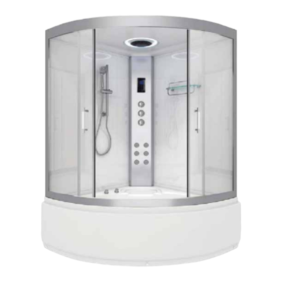
- Page 1 INSTALLATION AND OPERATING MANUAL *image for illustration purposes Lisna Waters Steam Shower Whirlpool Bath LWST: 1350mm x 1350mm INSTALLERS PLEASE NOTE, THESE INSTRUCTIONS ARE TO BE LEFT WITH THE CUSTOMER Technical Support: 0333 344 1109...
- Page 2 Thank you for purchasing this product. To guarantee the product delivers a long service life, please tted and used in accordance with the instructions contained in this booklet. Please check that the boxes contain all the items listed below, and report to us any parts that are missing or damaged prior to assembly and within 48 hours of receipt.
- Page 3 Contents Product Contents List with Images Important Notice Before you Begin Assembly Fitting the Shower Valve Leveling and Fitting the Tub Fixing the rear panels Central Tower Installation Front Frame Assembly Installing Fixed Side Glass Panels Glass Retaining Clips Shower Ceiling Temperature Sensor Runner Wheels Door Handles...
- Page 4 Lisna Waters Steam and Whirlpool Shower Contents Below is a list of the parts you should have received for the installation of your shower. Please note that tted in place, such as the monsoon shower head, etc. Please note, the design er the same or greater functionality.
- Page 5 Tub Base with waste assembly and exible waste pipe t i f i f - tted. Two straight metal sections and two curved rail sections nish (Front Frame). Thermostatic shower valve and 2 braided hoses. Monsoon maybe included) ttings. Two Long Flapped seals and two slightly shorter, plus a pair of Magnetic door seals.
- Page 6 IMPORTANT NOTICE tting this product please read and understand the following: By commencing testing and installation of the unit you are agreeing to the Terms and Conditions set out by us and copies are available by contacting us by telephone (details on the cover of this manual).
- Page 7 Before you begin Tools needed to assemble this shower cabin: Electric screwdriver with a selection of heads, regular screwdrivers, pipe grips, spanners, spirit level, sharp knife and rubber mallet. Connection of the electrical supply and plumbing may require additional tools. There is a drill bit supplied with the kit, to allow either widening of holes or drilling new holes which you feel cannot be located during construction.
- Page 8 Assembly Do not fi t the shower into locations where you do not have at least 40cm access all around the cabin both for installation and for future service access. We advise you do to fi t sinks, toilets etc that restrict access behind the shower.
- Page 9 1. FITTING THE SHOWER VALVE The Thermostatic Shower Valve will need to be fi tted into the central tower panel into the three pre-drilled, vertical holes available for it. First remove the 3 Chrome Dials from the valve. The Selector Dial and ON/Off Dial are removed by unscrewing the Chrome Lug on the side.
- Page 10 2. LEVELING AND FITTING THE TUB Remove the protective fi lm covering the tub base. Connect the soil pipe, trap and any couplings to the fl exible waste under the tub. You may choose to fi t either a HEPV0 trap with the appropriate couplings or choose to fi t a McAlpine ST28M coupling to a McAlpine 28-NRV trap.
- Page 11 2 Persons Required Section 3. FIXING REAR GLASS PANELS The two rear, framed glass panels are labeled LEFT and RIGHT as you would face the shower. Position xing holes is positioned to the rear. with the screws only, so you MUST support them until the next stage. rst to ensure all screws nd their correct position before then tightening them all fully.
- Page 12 4. CENTRAL TOWER PANEL er up the central tower panel from the inside of the cabin between the two rear panels. Moving to the rear of the cabin, adjust the Tower Panel to align the holes in the long vertical edge of the tower with those in the back panels.
- Page 13 5. FRONT FRAME Locate the two silver coloured upright frame sections and the two curved frame rail sections. You will need the 8 x LONG screws to join these sections together. The upper rail is deeper height than the lower rail. Align the upright with two holes in, to the upper curved rail.
- Page 14 6. INSTALLING THE FIXED SIDE GLASS PANELS Remove the SEAL TRIM that is located in the inside edge of the lower curved rail. It is held in position by two screws. Remove this trim to help you fi t the fi xed side glass panels.
- Page 15 7. GLASS RETAINING CLIPS Now both glass panels are fully inserted into the uprights you can tighten up the four corners of the silver framework which will not hold the glass in position. t the Retaining Clips to hold the the inside of the upper and lower rails, mark the x a screw to hold the clip in place.
- Page 16 9. SHOWER CEILING lm from the roof/ceiling. t the monsoon rain shower head into the centre of the roof. It is held in place with a retaining nut located on the outer/ upper face of the roof. tted. Ensure all the cables are unraveled to enable location and connection at a later stage.
- Page 17 10. STEAM TEMPERATURE SENSOR temperature sensor that monitors the internal cabin temperature. The temperature is selected on the control panel. When the internal cabin ned temperature it stops steam production until the temperature falls below, whereupon it re-activates the steam production again.
- Page 18 (image based on top cam fi tting) To fi t each of the cams, fi rst select the appropriate cam for the position on the door: 4 x Push button/Quick release for the lower position on the doors. 4 x Standard non push button for the upper position on doors. Position the Cam Body on the outside facing side of the door (curve pointing outwards).
- Page 19 12. FITTING THE DOOR HANDLES Each of the two shower doors requires a pair of chrome fi nished door handles to be fi tted. Each handle is comprised of several parts. Position the main handle part on the outside of a door ensuring the Chrome Washer and a Clear Washer are positioned also on the outside face over the thread.
- Page 20 14. HAND SHOWER AND RISER You are now ready to assemble and connect the hand shower. The hand shower comprises of: Multi function hand shower Chr ome nished riser bar Hand shower holster Chrome water hose Rear retaining nut Fitting screw The lower part of the riser bar has a threaded water connection.
- Page 21 15. GLASS SHELF Assemble the shelf fully before tting into the shower. Position the lower chrome rail over the holes in the glass on the underside of the shelf with the silver grommets positioned between the two. On the upper side of the glass, pass the bolt through a washer and through the hole in the glass and fasten into the end of the lower rail.
- Page 22 17. SHOWER VALVE The shower valve can be accessed from the rear of the shower and is located on the central tower. The valve is divided into three parts that are joined together. The uppermost part is the divertor. There are four connections able to be made here.
- Page 23 18. SHOWER SEALS This shower comes with 2 fl apped shower seals and a pair of magnetic doors seals. FLAPPED SEALS These seals fi t over the long side of the shower doors on the opposite side to the fi tting of the handles. MAGNETIC SEALS The magnetic seals fi t onto the doors along the long edge of the glass door nearest the handles..
- Page 24 Water Connections This product requires a hot and cold water supply. Your Hot and Cold water supply pipes should ideally be fi nished about 1 meter above the fl oor centrally in the corner and fi nished with 15mm compression fi ttings.
- Page 26 Whirlpool System The Whirlpool sysem operates independently from the system shown above and is pre-installed, requiring a separate 13amp power supply via the cable located from the whirlpool pump...
- Page 27 Models now now include 6 body Jets Steam Generator ST28M coupling to a McAlpine 28-NRV trap. A HEPV0 trap is highly recommended...
- Page 28 Electrical Connections STEAM GENERATOR & ELECTRONIC CONTROL MAIN POWER UNIT This Steam Shower requires connections to MAINS This model has a separate Steam Generator ELECTRICITY. and Electronic Control Unit. Both parts have a Data Cable to provide electrical communication The Steam Generator is 3kw rated and the between each part and a Power transfer Whirlpool Bath uses a 1 Horse Power Pump.
- Page 29 Sealing the Shower We recommend that you seal the shower internally In most cases sealant need only be applied to with a good quality bathroom sealant to provide the areas marked in SOLID RED on the diagram, an extra level of water proofi ng. however you may choose to seal on additional places on the shower.
- Page 30 Final Testing Check and test that each outlet function (hand shower, body jets and monsoon) work as expected by rotating the DIVERTOR DIAL (top chrome dial). markings. Check the Temperature can be increased and decreased by turning the lower chrome shower valve dial. Test that the button can be pressed at 38 degrees to turn the dial to the hottest settings.
- Page 31 Valve Operation There are 3 control dials inside your Shower Cabin. These dials control the output functions, water fl ow and temperature of your shower. The top dial can be turned to allow you to choose which output you wish to use: Body Jets, Overhead (Monsoon) Shower and Hand Shower.
- Page 32 Electronic Control Panel Your steam shower is tted with an electronic control panel that allows you to operate the electronic features of your shower. From the control panel you can control the lights, Steam, Radio, and Bluetooth audio. Power ON / OFF In standby mode this button is lit Red.
- Page 33 Bluetooth Pairing Before you can start streaming Audio to your 5: After a small amount of time you should see shower you must fi rst establish a connection the device name of the shower appear “ SPROUT”. between the shower and the device that will Select this to complete the Pairing of the two stream the audio to the shower;...
- Page 34 If you need a replacement part for your product, please call us on 0333 344 1109 with the details of your product. Please ensure you have your order number and supplier at hand. To nd parts for your product after the Guarantee has expired, please email info@lisnawaters.co.uk...
- Page 35 Thermostatic Cartridge Your shower is fi tted with a Thermostatic Cartridge. Should you need to remove or replace the cartridge for maintenance or replacement, follow the instructions below. Q: I am having to turn the dial round as far as it will go to the hottest setting and the water is only just warm.
- Page 36 With the Chrome dial removed you will see a plastic ring covering with the Thermostat underneath. Note down the position the ring is placed in. Pull the plastic ring (Temperature safety lock) towards you to remove. Keep this part safe You will now see the head of the Thermostat clearly visible.
- Page 37 WATER TIGHTNESS TEST To ensure that you will have no leaks from your shower it is essential to perform a water tightness test. With all connections fully tightened, hoses checked, jets fully sealed, your shower still roughly 18 inches from its designated space and the silicone sealer fully cured for at least 24 hours.
Need help?
Do you have a question about the LWST and is the answer not in the manual?
Questions and answers