Boss Audio Systems MGR350B User Manual
Bluetooth enabled
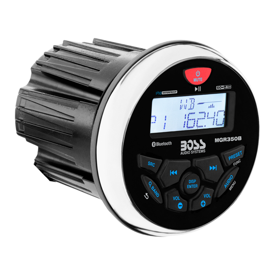
gauge hole radio
Hide thumbs
Also See for MGR350B:
- User manual (2 pages) ,
- User manual (16 pages) ,
- User manual (2 pages)
Advertisement
Quick Links
USER MANUAL
QUICK INSTALLATION GUIDE
MGR350B
MGR350B Bluetooth Gauge Hole Radio
Please read thorough these instructions
carefully so you will know how to operate
After you have finished reading the instructions,
keep this document in a safe place
USB
50w x4
DISP
ENTER
VOL
VOL
MGR350B
(1pc)
BLUETOOTH
ENABLED
®
GAUGE HOLE RADIO
User Manual
(1pc)
The Bluetooth® word mark and logos are registered trademarks
FEATURING ZERO
owned by Bluetooth SIG, Inc. and any use of such marks is under
STANDBY CURRENT DRAIN
license. Other trademarks and trade names are those of their
respective owners.
USER MANUAL
This device complies with part 15 of the FCC Rules. Operation is
subject to the following two conditions:
QUICK INSTALLATION GUIDE
(1) this device may not cause interference, and
(2) this device must accept any interference, including interference
MGR350B
that may cause undesired operation of this device.
This transmitter must not be co-located or operated in conjunction
BLUETOOTH
GAUGE HOLE RADIO
®
with any other antenna or transmitter. The Bluetooth antenna cannot
be removed (or replaced) by user. This equipment complies with
FCC/ IC radiation exposure limits set forth for an uncontrolled
environment and meets the FCC radio frequency (RF) Exposure
Guidelines and RSS-102 of the IC radio frequency (RF) Exposure
rules. This equipment has very low levels of RF energy that it
deemed to comply without maximum permissive exposure
evaluation (MPE). But it is desirable that it should be installed and
operated keeping the radiator at least 20 cm or more away from
person's body (excluding extremities: hands, wrists, feet and
ankles). Alteration or modifications carried out without appropriate
authorization may invalidate the user's right to operate the
equipment.
NOTE:
This equipment has been tested and found to comply with
the limits for a Class B digital device, pursuant to Part 15 of the FCC
Rules. These limits are designed to provide reasonable protection
against harmful interference in a residential installation. This
iPod
®
and iPhone
®
are registered trademarks of Apple Inc.
equipment generates, uses and can radiate radio frequency energy
registered in the USA and other countries.
and, if not installed and used in accordance with the instructions,
BOSS Audio Systems is not affiliated with Apple Inc.
may cause harmful interference to radio communications. However,
there is no guarantee that interference will not occur in a particular
installation. If this equipment does cause harmful interference to
radio or television reception, which can be determined by turning
the equipment off and on, the user is encouraged to try to correct
the interference by one or more of the following measures:
•
Relocate or reorient the receiving antenna.
BOSS Audio Systems
•
Increase the separation between the equipment and receiver.
3451 Lunar Court • Oxnard, CA 93030
•
Connect the equipment into an outlet on a circuit different from
www.bossaudio.com | 1.805.751.4853
that to which the receiver is connected.
Tech Support: www.bossaudio.com/support
•
Consult the dealer or an experienced radio/TV technician for help.
Copyright © 2015 AVA Enterprises Inc.
ADJUSTMENT OR ALTERATIONS OF THIS DEVICE MAY
RESULT IN HAZARDOUS RADIATION EXPOSURE.
0215
VER:1.0 EN
PRINTED IN CHINA
1
Thank you for purchasing this
IMPORTANT SAFETY PRECAUTIONS
BE SURE TO OBSERVE THE FOLLOWING GUIDELINES:
•
Do not turn up the volume so high that you can't hear what's
around you.
your model properly.
•
Use caution or temporarily discontinue use in potentially
hazardous situations.
for future reference.
•
Do not operate mobile video equipment while driving a motorized
vehicle – safe driving and safety consideration of others should
always be your highest priority.
THIS PACkAGE CONTAINS
•
Set your volume control at a low setting, then slowly increase the
sound until you can hear it comfortably without distortion, or ear
discomfort.
•
In the event you should notice smoke, strange noises or odor from
this product, or any other abnormal signs, immediately turn off the
Metal Bracket
Hexagon Mounting Studs
M4 Secure Nuts
power and consult your dealer or the nearest authorized
(1pc)
(2pcs)
(8pcs)
BOSS AUDIO Service Center
may result in permanent damage to the system.
2
Warranty Card
Facebook Card
(1pc)
(1pc)
INFORMATION TO THE USER
1
Make the mounting hole size as follows
FCC COMPLIANCE STATEMENT
4
Slip the unit through the hole cutout and into U-bracket
6
Secure and waterproof the wiring
!! WARNING !!
BEFORE YOU START
INSTALLATION PRECAUTIONS
Always consult with a professional installer
•
Do not attempt to install or service this product by yourself.
Installation or servicing of this product by persons without
professional training and experience in electronic equipment and mo-
torized vehicle accessories may be dangerous and could expose you
to the risk of electric shock, injury or other hazards
•
Refer any repairs to a qualified
BOSS AUDIO SYSTEMS
Center
•
The MGR350B should be wired directly to a vehicles battery
•
When wiring directly to the vehicles battery, be sure to disconnect
the batteries negative terminal wire before starting any wiring pro-
cedures, if extending the main power primary wire, it is suggested
that an optional fuse and fuse holder (not included) with minimum
rating of
20 Amperes be in-line with the positive battery terminal
•
The ground cable length should be as short as possible, if extend-
ing from you battery, be sure to use a proper gauge rating for the
length of the run, use only high quality copper primary type wire
Using this product in this condition
•
The MGR350B has a IPX6 weather resistant design, it should not be
submerged in or under water under any circumstances
•
Use only the installation parts provided with the MGR350B
SUGGESTED MOUNTING METHODS
CAUTION!!
3.00" / 76mm
Using other mounting methods may void
this warranty
2
Install studs mounts into rear of chassis
3
Adjust M4 nuts for the best mounting depth
Snap off break-away tabs to best fit
your applications depth
5
Firmly tighten remaining M4 nuts
TOOLS NEEDED:
- Measuring Tape / Ruler
- Wrench and/or Pliers
- Hole Saw
- Crimp Tool
To avoid potential shorts in the electrical
system, be sure to disconnect the (–)
battery cable before installation. Use this
unit with a 12-Volt battery and negative
grounding only. Failure to do so may result
in a fire or malfunction.
Service
When replacing the fuse, be sure to only use a
fuse of the rating specified on this product. To
avoid short-circuiting, cover any disconnected
leads with insulating tape. It is specially impor-
tant to insulate any unused wires, which if left uncovered may cause a
short circuit. When connecting other devices to this product, refer to
the manual for the product to be connected. The black cable is ground,
make sure to connect the ground wire first.
Ensure that the ground cable is properly connected to metal parts of
the vehicles body frame or direct to the battery if your vehicle does not
have a grounded chassis frame. The ground cable of this units power
amp and a second powered system must be connected to the frame
separately with different screws. If the screw for the ground wire
loosens or falls out, it could result in fire or malfunction.
3
WIRE DIAGRAM
Red
Right
Aux-In
White
Left
Yellow
Subwoofer
Red
Right
Rear Line Out
White
Left
Black
Red
Right
Front Line Out
YOUR
White
Left
ANTENNA
Grey
Antenna
Replace Fuse
Fuse Box
with AGU
USB
type only
15A
INSERT
YOUR
USB CABLE
FOR CHARGING ONLY: Cell Phone and iPod
Media Playback Not Supported
OPTIONAL DIRECT BATTERY WIRING CIRCUIT
Recommended
20A
12 ~ 14ga
BLACK
Primary Wire
(not included)
Battery Kill Switch
Fuse and Fuse Holder
(not included)
Ground wire
(not included)
BATTERY
Chassis
ground
point
Chassis
ground
point
Metal frame
CAUTION!!
Do not ground or short the speaker leads
TROUBLE SHOOTING GUIDE
TROUBLE
CAUSE
SOLUTION
The fuse is blown
Check / replace the fuse
Unit will not turn on
Ignition not engaged
Turn ignition to on position
Blown speaker
Replace faulty speaker
Volume is low / muted
Press the volume level up
Check your devices playing /
No sound is heard
Device is paused or muted
volume status
Refer to the user manual of the
The Bluetooth function of the
device for how to enable the
device is not enabled
Bluetooth function
The MGR350B BT memory
Follow how to reconnect a
Cannot pair Bluetooth
is full
device in section D
Move the device closer to the
The audio quality is poor
audio system or remove any
after connection with a
obstacle between the device
Bluetooth enabled device
The Bluetooth reception is poor
and the systems antenna
Adjust sub level to preferred
Sub level is muted
level
Sub woofer is not playing
Sub out is not enabled
Follow steps in section H
Disconnect power for
Power glitch or interference
10 seconds to reset
Charge battery, run the engine
Low battery power
to recharge the battery
Unit has become
unresponsive
Reset the main system
Follow steps in section H
TECHNICAL SUPPORT
1-805-751-4853
www.bossaudio.com/support
SPECIFICATIONS
FM TUNER FREqUENCY RANGE
INTEGRATED AMPLIFIER
•
USA
87.5~107.9MHz
•
MOSFET
•
Europe
87.5~108MHz
•
MAX Continuous Output: 240W
•
Asia
87.5~108MHz
(All channels driven)
1A
•
Australia 87.5~108MHz
•
PEAK Power Rating: 63W / channel
•
Usable Sensitivity: 12dB (S/N=30dB)
•
RMS Total Power Output: 150W
CHARGING MAX
•
Bands: 2
•
Channels: 4
•
Class: AB
•
Frequency Response: 20-25kHz
AM TUNER FREqUENCY RANGE
•
USA
530~1710KHz
•
4Ω stable
•
Europe
522~1620KHz
•
Asia
522~1620KHz
CHASSIS
•
Australia 522~1620KHz
•
Chassis Dimensions HxDxW :
•
Usable Sensitivity: 40dB (S/N=20dB)
0.79"x 3.75" x 3.5" / 20mm x 95mm x 90.2mm
•
Bands: 1
•
Button Backlight Illumination: RED LED
•
FRONT/ REAR RCA Preamp Output: 2V
RMS
WEATHER BAND SELECTION
•
CH.1 162.400MHz
•
RCA Input Impedance: 10kΩ
•
CH.2 162.425MHz
•
TFT: TN Type / Active Matrix
•
CH.3 162.450MHz
•
CH.4 162.475MHz
GENERAL
•
CH.5 162.500MHz
•
Power Source: 14.4VDC
•
CH.6 162.525MHz
(10.8V ~ 16V allowable)
•
CH.7 162.550MHz
•
Grounding System: Negative type
•
Bands: 1
•
Maximum Current Consumption: 15A
•
3-way protection circuitry (thermal,
overload, and speaker short protection)
BLUETOOTH
•
BT: 4.0
•
Unit Weight: 1.08lbs / 0.52kg
•
BT Range: 33Ft / 10M (Class 2)
•
Storage Temperature: 5
F to 113
o
•
BT Profiles: A2DP / AVRCP 1.3
-15
o
C to 45
o
C
•
Operation Temperature: 14
o
F to 104
-10
o
C to 40
o
C
USB DRIVE MEDIA SUPPORTED
•
MP3
•
Replacement Fuse: 15A
•
WMA
(Replace with ATG Fuse Type Only)
•
65,000 Songs
•
32GB / FAT 32
•
USB 2.0 High Speed
•
USB Output Voltage: 5VDC @ 1A
Specifications subject to change without notice
qUICk START GUIDE
F /
o
o
F /
Advertisement

Subscribe to Our Youtube Channel
Related Manuals for Boss Audio Systems MGR350B


Summary of Contents for Boss Audio Systems MGR350B
- Page 1 Reset the main system Follow steps in section H • The MGR350B has a IPX6 weather resistant design, it should not be may result in permanent damage to the system. amp and a second powered system must be connected to the frame submerged in or under water under any circumstances separately with different screws.
- Page 2 Long Press for Navigate Main Press ENTER To select through 4) When the connection is successful you will see CONNECTED on the MGR350B display and hear a confirmation When you press or hold the following button(s)... MAIN MENU options MENU Tree...
Need help?
Do you have a question about the MGR350B and is the answer not in the manual?
Questions and answers