
Summary of Contents for Mowin MSMART20H0B00
- Page 1 Manuale di istruzioni per l’uso INSTRUCTION MANUAL MODE D’EMPLOI BEDIENUNGSANLEITUNG MANUAL DE INSTRUCCIONES Инструкция по монтажу...
- Page 2 (see “Technical Data”) and to the installation instructions. Improper use or incorrect operation, itting or assembly can damage the system as well as cause injury to people and damage to property. The assembling instructions are available on the oficial web site http://www.comunello.com/mowin...
-
Page 3: Safety
2. SAFETY This installation manual is written exclusively for competent professional personnel. The installation, electrical connections and adjustments must be carried out conforming to good practice and according to the regulations in force. Incorrect installation can cause a potential hazard. The packing materials (plastic, polystyrene, etc.) must not be allowed to pollute the environment, but must be disposed of correctly, and must not be left within the reach of children since they can cause possible hazards. - Page 4 Cross-section of cables Max lenght of cables 1,50 mm² ~ 100 m 0,75 mm² ~ 50 m The device is not intended to be used by people (including children) whose physical, sensory or mental capabilities are reduced or by people who lack in experience or knowledge, unless a person responsible for their safety can control them or give them instructions concerning the use of the device.
-
Page 5: Technical Data
3. TECHNICAL DATA 3.1 Table of technical data and mark The CE mark certiies that the actuator conforms to the essential health and safety requirements laid down by European product directives. The CE mark can be identiied by the relevant adhesive label applied to the outside of the product, on which are shown some of the data shown in the following table: SMART Model... -
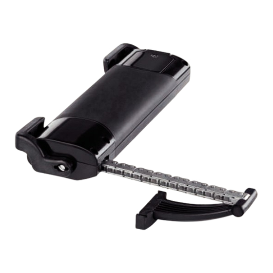
Page 6: Actuator
4. ACTUATOR 4.1 Types of power supply The smart series of actuators is available with electrical supply 230VAC 50 Hz (with a tolerance of ±10%), with a three-core supply cable: BLUE, neutral common; BLACK, open phase; BROWN, closed phase. 4.2 Calculation of the force necessary Key to symbols F = Force required to open in N (Newton) P = Weight of the window (only moveable part) in kg (kilogrammes) C = Opening travel of actuator in cm. -
Page 7: Installation
5. INSTALLATION With bottom-hung windows, there is a danger of potential injury resulting from the window accidentally falling. It is OBLIGATORY to it limiting arms (of the Series 1276 type), or an alternative safety system, of a suitable size to prevent the window from accidentally falling down. In case of testing before installation, please move the chain only when opening. - Page 8 Bottom-hung inward opening window: Top-hung outward opening window: CAUTION If the window is of the bottom-hung type, check that the limiting arms have been itted to prevent the window from accidentally falling down. Bottom-hung inward opening window: With a pencil, Top-hung outward opening window: With a pencil, mark mark the mid-point “X”...
- Page 9 Bottom-hung inward opening window: Top-hung outward opening window: Drill holes in the frame using the template supplied or the measurements shown on Page 7. Fix the brackets and the ixings, using suitable screws.
- Page 10 Bottom-hung inward opening window: Top-hung outward opening window: Insert the side fulcrum pin into the support bracket Move the actuator towards the window frame in order to insert the (opposite) side fulcrum pin into the support bracket Rotate the actuator, as shown in the following drawing, to ix it irmly...
- Page 11 Bottom-hung inward opening window: Top-hung outward opening window: Rotate the actuator so as to allow the window to shut. Rotate the actuator in the opposite direction so that the end of the Rotate the actuator in the opposite direction so that the end of the chain can be inserted correctly inside the bottom-hung window ixing.
- Page 12 Bottom-hung inward opening window: Top-hung outward opening window: Removal of end cap. Positioning the DIP-switch Dip-switch 1 Max (380) Min (180)
-
Page 13: 5.2 Electrical Connection
5.2 Electrical connection Wire in the apparatus according to the electrical supply required by the actuator (see label on product), following the table below. 230Vac Supply 24Vdc supply Blue Neutral / Common Blue Positive Black Phase / Open Brown Negative Brown Phase / Closed Electric 230Vac wiring... -
Page 14: Maintenance, Emergency Action & Cleaning
ATTENTION! Before operating the actuator, please make sure that the product has been ixed at the right position 6. MAINTENANCE, EMERGENCY ACTION & CLEANING If it becomes necessary to manually disconnect the window from the actuator due to: a power failure, mechanical breakdown, maintenance, or cleaning the exterior of the window, follow the step sequence described on Page 11 in reverse order. -
Page 15: Protection Of The Environment
7. PROTECTION OF THE ENVIRONMENT Some parts inside the actuator are not recyclable (plastic materials and electronic parts) and cannot be considered normal refuse. They must be disposed of correctly. In case of doubt, consult the relevant refuse disposal body. 8. -
Page 16: Guarantee
9. WARRANTY Fratelli Comunello SpA provides a warranty for thirty-six months for the correct functioning of the actuators from the date of manufacture, provided that the performance speciications indicated in the product instruction manuals are respected. Free of charge repair and replacement of components that are found to be faulty according to the indisputable judgment of the company’s technical staff shall be guaranteed at the sole discretion of Fratelli Comunello Spa, and so excluding any claim for damages made by others. - Page 17 DECLARATION OF EC CONFORMITY The company Fratelli Comunello S.p.A., based in Rosà, Via Cassola 64 (VI), Italy Declares under its full responsibility that the following actuators’ models: MSMART20H0*** • MSMART20L0*** • Serial number and year of manufacture: on the data plate. Description: electromechanical actuator for windows, skylights.
Need help?
Do you have a question about the MSMART20H0B00 and is the answer not in the manual?
Questions and answers