
Summary of Contents for Amoonsky AMS-MVP508
- Page 1 Shenzhen Amoonsky Technology Co., LTD Led Video Processor A series product manuals User Manual LED Video Processor AMS-MVP508 English...
- Page 2 Contents Introduction ............................... 1 About LED Video Processor ......................1 Feature ............................. 1 Panel ................................. 3 Rear Panel ............................3 Front Panel ............................4 Menu System ............................6 Menu Structure ..........................6 Operation menu ..........................6 Default menu ..........................7 Main menu ..........................
-
Page 3: Introduction
Introduction This manual contains information about how to use, install and configure the LED video processor, in addition, also relates to knowledge LED video processor and LED video systems. Users are LED video processor, please read this manual in detail. About LED Video Processor LED video processor is a mid-market seamless handover effects video processor, it supports high definition digital input, analog HD input, and can achieve all channels seamlessly switch audio and video... - Page 4 is disconnected or may be due to the case of no signal input to switch directly lead to errors, improve the success rate performances. Support PIP - PIP technology unaltered state in the original image, the other input of the same or different overlay images.
-
Page 5: Panel
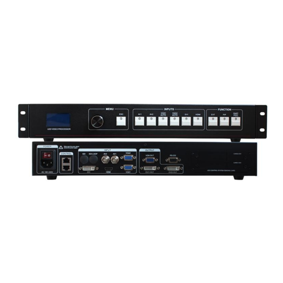
Panel Rear Panel Figure 1-Video processor rear panel »» AC Power Input - using IEC standard power cable video processor, the input power is 100-240 VAC, 50-60Hz. »» Video Input - processor can receive digital video signals, the analog video signal, a CVBS video signal, the following criteria for each input interface. -
Page 6: Front Panel
Front Panel Figure 3-Front Panel »» LCD display - Display menu and current information. »» Menu operation buttons - Menu operation keypad with "Return key" ,Knob "confirm and adjust." The following are included on each key. OK& ESC key, or return to the previous menu. Knob , press the OK button to enter the menu or submenu key to confirm the function. - Page 7 »» Function button area - function button area contains a wide mode, preset call, PIP and transition effects operating buttons can quickly achieve operating each function. Figure 5—Function ● PART button: Part of the screen display mode, the user settings menu, good splicing interception parameters section of the screen, press this button part of the screen to display the results.
-
Page 8: Menu System
Menu System Menu Structure Default menu Main menu Function Description Set the output resolution, precise adjustment of the OUTPUT output resolution Adjustment splice, equal splice or unequal or parts of SPLICE the image display Set PIP size, position, the input source IMAGE Adjust image color, brightness, contrast, etc. -
Page 9: Default Menu
Default menu The default menu after the device starts, LCD screen interface, shown above, the input source, the input source connected state, the input source is connected, the output resolution, mosaic mode, brightness and output audio channels and other information, shows the processing the main parameters menu system. -
Page 10: Reset
Output Resolution Using different resolution display or LED screen, to achieve point-to-point output, it is necessary to set the output resolution and the resolution of precise adjustment. 1. select a larger than screen resolution Default Menu → Main Menu →OUTPUT → Output resolution→ confirmed 2. -
Page 11: Splicing Applications
Splicing applications LED Video Processor has a powerful splicing, enabling hardware splicing 10x10 processors to achieve frame synchronization. There introduce it’s equal splicing and unequal Equal Splicing For example the following parameters of the LED screen wall Device Name Specification Parameter Other LED unit... -
Page 12: Unequal Splicing
3. are provided P1 ~ P4 video processor parameters. Since the processor comes with 1280x1024 / 60 resolution, so no need to further fine-tune. All of the following parameters, only the splice location is not the same. Processor P1、P2、P3、P4: 1. Set the output resolution Default Menu →... - Page 13 Display1 Display 2 Display 3 Display 4 DVI-OUT DVI-OUT DVI -INPUT Figure 11 -Unequal Splicing Steps: 1.Refer to Figure 14 Connect all devices. 2.Sending card S1 and S2 cascade, S3 and S4 cascade. Respectively adjustment LED screen software Display 1 and Display 3 into a complete display area, Display 2 and Display 4 set another full display area.
-
Page 14: Capture
Processor P2: 1.Setting resolution Default Menu → Main Menu → OUTPUT →Resolution→1280x720 60Hz Default Menu → Main Menu → OUTPUT→Width→1280 Default Menu → Main Menu → OUTPUT→Height→896 2. Setting splice Default Menu → Main Menu →SPLICE→ MODE →V-Wall Default Menu → Main Menu →SPLICE→ Pattern →Unequal Default Menu →... -
Page 15: Keying
PIP is the use of digital technology to display two programs on the same screen. That is the normal viewing of the main screen, while the insertion of one or more sub-picture compressed in order to appreciate the main screen while monitoring other channels. When operating in PIP mode mode, the user must provide at least two of the input signal, and the PIP menu settings accordingly. -
Page 16: Preset
Setting step: Default Menu → Main Menu → PIP → PIP mode→Keying Default Menu → Main Menu → PIP→Keying Setup→ Input→ DVI Default Menu → Main Menu → PIP→Keying Setup→ Chroma Key→ Black Preset Preset is to facilitate users to use quickly recall commonly used in a variety of scenarios, reducing the user when the operation is repeated complicated settings, improve work efficiency. -
Page 17: Key Lock
NOTE: The same type of signal can not be pre-selected, otherwise it will prompt "invalid channel!" Conflict pre-selected signal PIP input signal and the same conflict, a detailed check list of the PIP conflict. Brightness and Contrast Processor technology unique brightness, contrast adjustment, adjust color reproduction and high brightness after the picture level without loss. -
Page 18: Audio And Video Synchronization
Audio and video synchronization Video processor provides eight channels of video and 4 audio, there are three-way external audio input and 1 channel audio input HDMI audio. So switching to a set of audio output. Follows Set the current corresponding audio and video channels. In the default menu, use the ↑ and ↓ buttons to toggle IN1 ~ IN3, HDMI, a total of 5 off the total state.
Need help?
Do you have a question about the AMS-MVP508 and is the answer not in the manual?
Questions and answers