
Related Manuals for Tyco CPS6000

Summary of Contents for Tyco CPS6000
- Page 1 CPS6000 -48V Indoor/Outdoor Power Shelf Product Manual Select Code 167-102-105 Comcode 108992120 Issue 16 May 2006...
- Page 2 1:1D Notice: The information, specifications, and procedures in this manual are subject to change without notice. Tyco Electronics assumes no responsibility for any errors that may appear in this document. © 2006 Tyco Electronics Power Systems, Inc. (Mesquite, Texas) All International Rights Reserved...
- Page 3 CPS6000 –48V Indoor/Outdoor Power Shelf Table of Contents 1 Introduction......................6 Overview........................6 Customer Service Contacts ..................8 2 Product Description ....................9 CPS6000 System Overview..................9 Block Diagrams ......................10 Shelf Design......................13 Configurations......................14 Distribution and Power Module Configurations.............15 Battery Reserve System ..................16 Specifications......................17 3 Engineering and Ordering ..................25 Engineering Information..................25...
- Page 4 T1.317 Command Language.................166 Appendix B: Battery Functions ................190 Float Mode ......................190 Slope Thermal Compensation................190 Plant Battery Test....................193 Boost Mode......................194 Appendix C: Alarms and Relays ................197 Alarm Relays ......................197 Alarms........................197 Appendix D: EasyView for Windows® for the CPS6000 Controller....202 Issue 16 May 2006...
- Page 5 CPS6000 –48V Indoor/Outdoor Power Shelf Overview.......................202 Loading the EasyView Application ..............202 Making the Connection..................202 Configuring a Site ....................203 Serial Port Setup ....................203 Connect to Site......................203 Navigating Once Connected .................204 Appendix E: Pigtail Alarm Cable................206 Appendix F: Operating Temperature Measurement and Vertical Spacing..209 Overview.......................209...
-
Page 6: Introduction
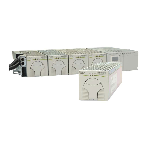
Figure 1-1: CPS6000 System with Distribution Module The CPS6000 currently supports -48V primary loads up to 8.2kW of N+1 redundant power in a single 19-inch shelf, and up to 10.9kW of N+1 redundant power in a 23-inch shelf with a Bulk Output Module and 50A rectifiers. - Page 7 CPS6000 –48V Indoor/Outdoor Power Shelf CPS6000 systems may include up to 4 bulk-output shelves: an Initial shelf with controller, and up to three supplemental shelves. External distribution is used with multi-shelf systems. Ringer Chassis may be installed in Power Slots. Each Ringer Chassis supports one ringing output in either non-redundant (simplex) or 1 + 1 redundant (duplex) operation.
-
Page 8: Customer Service Contacts
Customer Training Tyco Electronics offers customer training on many Power Systems products. For information call 1-972-284-2163. This number is answered from 8:00 a.m. until 4:30 p.m., Central Time Zone (Zone 6), Monday through Friday. -
Page 9: Product Description
Several types of distribution modules are available. The Bulk Output Module provides connection to an external distribution without consuming a shelf power slot. The CPS6000 is available as single-shelf systems and multiple-shelf systems with both 19- inch and 23-inch shelves. -
Page 10: Block Diagrams
Remote Distribution Module (RDM). Block Diagrams 2-1a and 2-1b are basic block diagrams of the CPS6000 System in a single shelf with a Distribution Module. Figure 2-2 shows the Bulk Output Module in place of the Distribution Module. - Page 11 CPS6000 –48V Indoor/Outdoor Power Shelf Figure 2-1a: CPS6000 System with Distribution Module Issue 16 May 2006...
- Page 12 CPS6000 –48V Indoor/Outdoor Power Shelf Figure 2-1b: CPS6000 System with Distribution Module Issue 16 May 2006...
-
Page 13: Shelf Design
CPS6000 –48V Indoor/Outdoor Power Shelf Figure 2-2: CPS6000 System with Bulk Output Module Shelf Design Features • The shelf is available in 19-inch (phase 2) and 23-inch standard widths and has the following features: • Accepts plug-in rectifier, ringer and Distribution Modules. -
Page 14: Configurations
The 23-Inch Shelf provides five Power Slots. Power Slots support Rectifiers, Ringer Chassis, and Distribution Modules. Figure 2-3 shows the show the locations of the CPS6000 components in the19-inch and 23-inch shelves with the Single-Slot Distribution Module. Figure 2-3: CPS6000 Systems with Single-Slot Distribution Module... -
Page 15: Distribution And Power Module Configurations
CPS6000 –48V Indoor/Outdoor Power Shelf Distribution and Power Module Configurations The 19-inch shelf has four Power Slots, and the 23-inch shelf has five Power Slots for power modules (Rectifiers and up to two Ringer Chassis) and distribution options (See 2- 4). With Bulk Output Distribution only, all slots are available for power modules. -
Page 16: Issue
Battery Reserve System Introduction A battery reserve system is a key component for a reliable power system. The CPS6000 provides a primary voltage of -48Vdc that drives load equipment. At the same time, it provides float and recharge capability for the battery reserve system. If an ac power failure occurs, the batteries provide power to the load equipment until the ac can be restored. -
Page 17: Specifications
CPS6000 –48V Indoor/Outdoor Power Shelf Specifications Table 2-A: CPS6000 System Specifications Shelf Single 19-inch or 23-inch shelf Power Slots per Shelf 4 (19-inch shelf), 5 (23-inch shelf) Power Units Max. per Power Slots Installed Position Unit Shelf Each Installed from the Right... - Page 18 Rectifiers Installation Category CPS6000 is suitable for connection to ac utility systems where the expected level of lightning surges complies with ANSI C62.41 Category B or IEC 60664-1 Overvoltage Category II. A service entrance surge protector is required in applications where the installation categories can not be classified as being compliant to either ANSI C62.41 Category B or IEC 60664-1...
- Page 19 CPS6000 –48V Indoor/Outdoor Power Shelf Table 2-B: CPS6000 Physical Specifications Height Width Depth Weight in. (mm) in. (mm) in. (mm) lb (kg) Rectifier 3.41 (86.6) 3.4 (86.3) 11.2 (284.5) 5.75 (2.6) Ringer Chassis 3.41 (86.6) 3.4 (86.3) 11.2 (284.5) 3.45 (1.6) Ringer 2.4 (61.0)
- Page 20 CPS6000 –48V Indoor/Outdoor Power Shelf 132W (450 BTU) per QS861A rectifier at full load and 120 Vac operation; 212W (724 BTU) per QS862A at full load and 240 Vac operation; 130W (445 BTU) per QS861A rectifier at full load and 240 Vac operation;...
- Page 21 CPS6000 –48V Indoor/Outdoor Power Shelf Output Current 0 to 15A at 54.5V Nominal Input Voltage 100/120/200/208/240 Vac (Shutdown from 135 to 150V) Input Voltage Ranges 85 to 275 Vac Input Current 8A at 120 Vac 4.4A at 208 Vac Operating Frequency Range...
- Page 22 CPS6000 –48V Indoor/Outdoor Power Shelf Output Voltage Regulation ±0.5% Output Noise, Ripple 250 millivolts peak to peak maximum, over the range dc to 100 MHz Load Share Accuracy 1.5A maximum deviation between rectifiers Heat Dissipation (per rectifier, full load) 212W (724 BTU) at 200 to 240 Vac operation Power Factor >0.98 for loads >...
- Page 23 CPS6000 –48V Indoor/Outdoor Power Shelf Selective High-Voltage Shutdown Above 58 Vdc Backup High-Voltage Shutdown Above 60 Vdc for 1 millisecond Table 2-J: QS865A Rectifier Specifications Nominal Output Voltage 48/52/54.5 Vdc Operating Output Voltage Ranges 42 to 58 Vdc Boost Voltage...
- Page 24 CPS6000 –48V Indoor/Outdoor Power Shelf Thermal Limiting Output VA may be reduced by reducing Vac when operating simultaneously above 50°C and less than -50Vdc input. Vac is reduced only sufficiently to prevent damage to the ringer. Load Power Factor Operating: 0.5 Leading to 0.9 Lagging No Damage: 0 Leading to 0.7 Lagging...
-
Page 25: Engineering And Ordering
CPS6000 –48V Indoor/Outdoor Power Shelf 3 Engineering and Ordering Engineering Information Introduction This section discusses the factors to be considered in determining the number of rectifiers and ringers required in both non-redundant and redundant battery plants. Rectifier Sizing (Non-Redundant Systems) - Page 26 CPS6000 –48V Indoor/Outdoor Power Shelf Figure 3-1: Recharge Factor vs. Recharge Time Plant Configuration Examples 1. To illustrate the relationships between mirc, abh current drains, the recharge factor, and battery recharge current for non-redundant and redundant systems, consider the following examples.
-
Page 27: Ordering Information
Ringers in each Ringer Chassis. Ordering Information Ordering Guide An ordering guide may be downloaded from the Tyco Electronics Power Systems web site. This guide will augment the information found here. To download, go to http://power.tycoelectronics.com/es_cps6000.html and click on the CPS6000 System Ordering Guide link. - Page 28 CPS6000 –48V Indoor/Outdoor Power Shelf Distribution Module Lugs The 3.4-inch wide Distribution Modules require M5 double hole lugs on 5/8-inch centers for battery breaker and CO ground connections. Straight lugs may be used for most applications. Office Alarm Cable WARNING Disconnect alarm cable before cutting it to length.
- Page 29 Rectifiers The constant-power rectifiers each occupy a single slot in the CPS6000 shelf. If a full complement of rectifiers is not required, a rectifier slot filler may be to cover empty rectifier slots. The slot filler is not necessary from an earthquake standpoint. Check with Sales Team...
- Page 30 AC Power Cables An ac power cable must be ordered. A standard ac cable set will not fit in the CPS6000 shelf. Verify that the sum of the input currents for all the rectifiers served by an ac circuit breaker does not exceed 80% of the breaker’s rating.
- Page 31 CPS6000 –48V Indoor/Outdoor Power Shelf Table 3-A: Shelf AC Input Current Table, Minimum Size CB or Fuse QS860A – 500W rectifier (prelim) 120 Va 240 Vac 23-in. shelf with 5 power slots, dual feed 20A feed 1, 15A feed 2 15A feed 1, 15A feed 2 23-in.
- Page 32 CPS6000 –48V Indoor/Outdoor Power Shelf Table 3-B: Shelf AC Input Current Table, Minimum Size CB or Fuse (continued) QS862A – 25A/30A rectifier 120 Va 240 Vac 23-in. shelf with 5 power slots, dual feed 50A feed 1, 35A feed 2 35A feed 1, 25A feed 2 23-in.
- Page 33 CPS6000 –48V Indoor/Outdoor Power Shelf Table 3-C: Rectifier AC Input Current Table Minimum Circuit 75°C Minimum Breaker value Recommended Model Nominal Number of Tyco Number of Input Rectifiers Nominal AC recommended Wire Gauge Rectifier (A) Rectifier Voltage per AC feed...
- Page 34 CPS6000 –48V Indoor/Outdoor Power Shelf Remote Distribution Monitor Module The Remote Distribution Monitor Module allows the CPS6000 system controller to monitor for open circuit breakers and fuses, monitor current through a battery shunt, and monitor/control low-voltage disconnect contactors at an external distribution panel that is bulk-fed from the CPS6000 system.
-
Page 35: Safety
The CE Mark demonstrates compliance with the European Union Council Directives for Low Voltage and EMC. • The CPS6000 platform is Underwriters Laboratories (UL) Listed per Subject Letter 1801, DC Power Distribution Centers for Telecommunications Equipment. • CPS6000 shelves equipped with QS820A ringers (in development) have hazardous secondary voltages on the secondary bus output connectors. - Page 36 In enclosed equipment cabinets, the CPS6000 mounting framework must be connected directly to the cabinet ac service ground bus. For applications in huts, vaults, and central offices, the CPS6000 mounting framework must be connected to the system integrated ground grid.
- Page 37 CPS6000 outputs are not connected to earth. Earthing of rectifier outputs may be performed externally to the shelf at a “ground window” or “mesh ground”. Connection of Ringer tip outputs to CPS6000 Battery or Ground is optional via Ringer Chassis jumper or external connection.
-
Page 38: Warning Statements And Safety Symbols
CPS6000 –48V Indoor/Outdoor Power Shelf Warning Statements and Safety Symbols The symbols may sometimes be accompanied by some type of statement; e.g., “Hazardous voltage/energy inside. Risk of injury. This unit must be accessed only by qualified personnel.” Signal words as described below may also be used to indicate the level of hazard. -
Page 39: Precautions
CPS6000 –48V Indoor/Outdoor Power Shelf Precautions When working on or using this type of equipment, the following precautions should be noted: • This unit must be installed, serviced, and operated only by skilled and qualified personnel who have the necessary knowledge and practical experience with electrical equipment and who understand the hazards that can arise when working on this type of equipment. -
Page 40: Special Installation Notes
CPS6000 –48V Indoor/Outdoor Power Shelf Special Installation Notes Deutsch Installationsanleitung Eingangsspannung ( Voltage ) : 2x AC 120/200-240V V Eingangsstrom ( Current ) : QS801A, max 45A, QS800A, max 30A Eingangsleistung ( Watts ) : Nennfrequenz ( Frequency ) : 50 / 60 Hz Seriennummer ( Assembly No. - Page 41 CPS6000 –48V Indoor/Outdoor Power Shelf Espanol Notas especiales para instalaciones en países de habla hispana • Instrucciones de instalación (Installation Instructions) • Voltaje (Voltage): Vea tabla 2-A • Corriente (Current): Vea tabla 2-A • Frecuencia (Frequency): 50/60Hz • Voltaje y corriente de salida (Output Voltage and Current): Vea tabla 2-A •...
-
Page 42: Installation
CPS6000 –48V Indoor/Outdoor Power Shelf 5 Installation CPS6000 Installation Purpose CPS6000 Shelf Installation guide for generic installations. Additional requirements are needed for application specific installations. Refer to Appendix F for spacing requirements. Audience Field application personnel. Precautions Observe ESD protection while installing circuit packs Safety •... -
Page 43: Installing The Cps6000 Shelf
There are two distribution options for the CPS6000, a Single-Slot Distribution Module and a Bulk Output Module. Only one distribution box can be used in a CPS6000 shelf. This hardware assembly is field installable, however in most cases the factory will have already installed the distribution module when it is required. - Page 44 CPS6000 –48V Indoor/Outdoor Power Shelf Step Action Insert one #4 Screw inside the left side of the Bulk Output Module, hand tight to approximately 5 in-lb. See Figure 5-2. Insert one #4 Screw on the right side of the shelf, hand tight to approximately 5 in-lb.
-
Page 45: Install The Cps6000 Shelf
• Thermal Probe Connection Leave a sufficient service loop on these cables. Install the CPS6000 Shelf Follow the steps in the table below to mount the CPS6000 shelf into a 19-inch or 23-inch frame. Step Action Locate the 2 mounting brackets, one on each side of the CPS shelf; align the holes in the shelf-mounting bracket with the holes in the mounting frame. -
Page 46: Controller
CPS6000 –48V Indoor/Outdoor Power Shelf Controller Controller Installation The Controller mounts in the controller housing located on the left side of the CPS shelf, Figure 5-5. The Controller is field installable, however in most cases it will be factory installed. - Page 47 CPS6000 –48V Indoor/Outdoor Power Shelf Figure 5-5: Controller Installation Issue 16 May 2006...
-
Page 48: Qs845A Supplementary Shelf Board
QS845A Supplementary Shelf Board Multi-Shelf Installations The QS845A allows up to four CPS6000 shelves to be paralleled. It can be used either with the QS840A or the QS841A controller. This board is installed in the controller position on supplemental CPS6000 shelves and enables the subsequent shelf equipment to communicate with the controller on the initial shelf. - Page 49 CPS6000 –48V Indoor/Outdoor Power Shelf Inter-Shelf Connection Refer to Figure 5-7 for the following procedure. Step Action Connect a shelf-interconnect cable from P5 (SYS AUX PORT) on the primary shelf controller to the shelf SHF 2 connector on shelf 2.
-
Page 50: Thermal Compensation Connections
CPS6000 –48V Indoor/Outdoor Power Shelf Thermal Compensation Connections Thermal Compensation The optional QS837A VT-Probes are used to measure battery temperature for slope thermal compensation, and to measure battery voltage for battery voltage imbalance detection when the Voltage Monitoring Module 108958422 card is used. There is a maximum 18 probes. - Page 51 CPS6000 –48V Indoor/Outdoor Power Shelf Figure 5-8: VT-Probe Connections to Controller Figure 5-9a: Connecting Battery Monitor Voltage Wire to Thermal Probe Cable Issue 16 May 2006...
- Page 52 CPS6000 –48V Indoor/Outdoor Power Shelf Figure 5-9b: Tie Wraps for strain relief and additional support Figure 5-9c: Connecting Thermal Probe Cable to the battery Issue 16 May 2006...
- Page 53 CPS6000 –48V Indoor/Outdoor Power Shelf Figure 5-10: VT-Probe/Battery Voltage Monitor Connections to Controller Issue 16 May 2006...
-
Page 54: Office Alarms
CPS6000 –48V Indoor/Outdoor Power Shelf Office Alarms An office alarm connector (J1) is provided on the QS840A/QS841A controller board. This connector provides access to the output of the alarm relays. Discrete wire and ribbon cable assemblies are available for making office alarm connections to the controller. -
Page 55: Controller Connections
Connection to the LAN is made by attaching standard Cat-5 cable from P5 to the appropriate 10/100Base-T LAN connection. The cable should be appropriately dressed out of the CPS6000 system to the LAN connection. The shroud of P5 has been terminated to chassis to accommodate the use of a shielded Cat-5 cable connection. - Page 56 CPS6000 –48V Indoor/Outdoor Power Shelf Step Action Insert the H569-470A ac cord into the ac receptacles on the CPS shelf. Refer Figure 5-12a, b, c or d for the appropriate shelf Terminate the supply end of the cable with an appropriate plug (plug not provided).
- Page 57 CPS6000 –48V Indoor/Outdoor Power Shelf Figure 5-12b: Single cord AC Input Connections Figure 5-12c: Dual AC Input Cord (10 Awg, 10 ft) Connections Issue 16 May 2006...
- Page 58 CPS6000 –48V Indoor/Outdoor Power Shelf Figure 5-12d: Rear AC Input Connections Issue 16 May 2006...
- Page 59 CPS6000 –48V Indoor/Outdoor Power Shelf AC Connections to External AC Distribution Panel Note: Each ac connection to the CPS6000 shelf is to be provided with circuit breaker protection at maximum 40A for a 23-inch shelf with dual ac feed and low-line (120V) input.
-
Page 60: C.o. Ground Conductor Installation
CPS6000 –48V Indoor/Outdoor Power Shelf C.O. Ground Conductor Installation C.O. Ground Conductor Installation Use an M6 double-hole lug on 5/8-inch center (Not provided) to terminate one end of the Central Office (C.O.) ground conductor to the CPS shelf. Terminate the other end of the conductor with a lug appropriate for the installation site. -
Page 61: Rectifier Installation
Rectifier Installation Install the Rectifier This procedure is used to install the rectifier in the CPS6000 shelf. Figure 5-15 is a 23-inch shelf with 4 rectifier positions and a Single-Slot Distribution Module. Note: All rectifier ac and dc connections are made when rectifiers are seated in the shelf. -
Page 62: Ringer Installation
Ringer Installation Install the Ringer Chassis and Ringer Modules This procedure is used to install ringer chassis’s and ringer modules in the CPS6000 shelf. Figure 5-16 shows a shelf, Ringer chassis and a Distribution Module. Up to two Ringer Chassis’s may be installed per shelf, one in each of the two right-most power slots to the left of the Distribution Section. - Page 63 CPS6000 –48V Indoor/Outdoor Power Shelf Note: No rectifiers may be installed to the right of a Ringer Chassis. Step Action Slide the ringer chassis into the power slot until the connector on the rear of the ringer chassis engages with the connector at the back of the power slot on the shelf. Verify the hook under the front left of the ringer chassis hooks under the shelf.
- Page 64 CPS6000 –48V Indoor/Outdoor Power Shelf Figure 5-17: Ringer Installation Step Action Use Tip Jumper J12 to set the Ringer output type. See Figure 5-16 for J12 Tip Jumper location. Note: Ringer output type is determined by connecting Ring Return (Tip) to Battery or Ground.
- Page 65 CPS6000 –48V Indoor/Outdoor Power Shelf Figure 5-18: Ringer Load Cable and Routing Issue 16 May 2006...
-
Page 66: Battery Strings Installation
Warning: If a battery disconnect switch is being used, mount the switch before proceeding and make sure it is in the OFF/OPEN position prior to making any connections. Connect Battery Strings This procedure is used to connect up to four battery strings to the CPS6000. Step Action... - Page 67 CPS6000 –48V Indoor/Outdoor Power Shelf Figure 5-19b: Battery String Connections Issue 16 May 2006...
- Page 68 CPS6000 –48V Indoor/Outdoor Power Shelf Figure 5-19c: Battery String Connections Issue 16 May 2006...
-
Page 69: Load Connections
CPS6000 –48V Indoor/Outdoor Power Shelf Load Connections Loads can be connected using 2 bullet-style circuit breakers, GMT fuses or Direct Bus Connections. Double-Slot Distribution Module Note Check if Double-Slot Distribution Module positions can be used for load positions, make connections as described here. Positions are converted from battery to a load positions using an adapter on the circuit breaker. - Page 70 CPS6000 –48V Indoor/Outdoor Power Shelf Figure 5-20a: Rear Load Connections Issue 16 May 2006...
- Page 71 CPS6000 –48V Indoor/Outdoor Power Shelf Figure 5-20b: Front Load Connections Issue 16 May 2006...
- Page 72 CPS6000 –48V Indoor/Outdoor Power Shelf Terminate Load Connections - GMT Fuses Single-Slot Distribution When using 20 A fuses adjacent fuse positions must be left open. No more than 80A may be carried through the 10 fuse positions, or 40A per half-section. Up to 14 AWG wire can be used to connect loads to each of the fuse positions.
- Page 73 CPS6000 –48V Indoor/Outdoor Power Shelf Figure 5-21: GMT Fuse Connections, Single-Slot Distribution Module Issue 16 May 2006...
- Page 74 CPS6000 –48V Indoor/Outdoor Power Shelf Figure 5-22: GMT Fuse Connections, Double-Slot Distribution Module Issue 16 May 2006...
-
Page 75: Circuit Breaker And Fuse Installation
CPS6000 –48V Indoor/Outdoor Power Shelf Circuit Breaker and Fuse Installation Figure 5-23 and 5-24shows the proper circuit breaker and fuse orientation for installation. Retention bracket may or may not be provided with all configurations. Figure 5-23: Circuit Breaker Retention Bracket... -
Page 76: Terminate Load Connections - Direct To Bus Connections
CPS6000 –48V Indoor/Outdoor Power Shelf Terminate Load Connections - Direct to Bus Connections The Distribution Module can be connected directly to the unprotected (no fuses or circuit breakers) dc output bus. Connections are made from the top of the unit. Lug covers are not provided they must be ordered separately. -
Page 77: Load Connections - Bulk Output
CPS6000 –48V Indoor/Outdoor Power Shelf Load Connections - Bulk Output Bulk Output Distribution Option Load connections are made to the Bulk Output Distribution Module as shown in Figures 5- 26a or 5-26b or 5-26C Figure 5-26a: Front Bulk Output Load Connections – up to 2Awg... -
Page 78: Battery And Load Connections - External Dc Distribution Panel
CPS6000 –48V Indoor/Outdoor Power Shelf Figure 5-26c: Rear Bulk Output Load Connections Battery and Load Connections - External DC Distribution Panel Battery Cable Connection Dress battery cables internal to the equipment frame up the right side of the frame to enter the top of a Group 163 distribution panel of H5694720 arranged for battery input. - Page 79 CPS6000 –48V Indoor/Outdoor Power Shelf Configure Additional Battery Inputs (optional) Configure the distribution panel for the additional battery inputs as required, in groups of four. Step Action Remove breaker terminal posts in groups of four. Install busbars. Remove jumpers and reinstall as shown to separate the alarm contacts between the battery input and load output sections.
- Page 80 CPS6000 –48V Indoor/Outdoor Power Shelf Figure 5-29: Install 4-String Battery Busbar Figure 5-30: Relocate Alarm Jumper Issue 16 May 2006...
- Page 81 CPS6000 –48V Indoor/Outdoor Power Shelf Figure 5-31: Jumper Locations in Completed 8-Position Configuration Issue 16 May 2006...
- Page 82 CPS6000 –48V Indoor/Outdoor Power Shelf Figure 5-32: Battery and Load Connections to Distribution Panel Issue 16 May 2006...
- Page 83 CPS6000 –48V Indoor/Outdoor Power Shelf Bullet Style Circuit Breakers Comcode Amperage CB Positions Min Wire Gauge 407998137 407998145 407998152 407998160 407998178 407998186 407998194 407998202 408213486 407998210 407998228 407998236 407998244 407998251 407998269 407998277 408185353 408185346 408564941 408535752 Issue 16 May 2006...
-
Page 84: Initial Start-Up
If using battery disconnect switches place them in their ON/CLOSED positions prior to applying ac power. Turn on the ac service circuit breakers to apply power to the CPS6000 power system. Verify that All LEDs on all components including rectifiers, controllers, LVD boards, and remote voltage monitor modules are green. - Page 85 CPS6000 –48V Indoor/Outdoor Power Shelf Serial Port The appropriate IP address, subnet mask, hostname, and default gateway IP address must be configured on the QS841A through serial port J3. To login to the QS841A, follow these steps: a. Start-up the PC terminal program (Windows Terminal, ProComm, etc.) using the following communication...
- Page 86 CPS6000 –48V Indoor/Outdoor Power Shelf CHA NET1,IP=ddd.ddd.ddd.ddd Verify by typing: STA NET1,IP • To set the Subnet mask, type: CHA NET1,SUB=ddd.ddd.ddd.ddd Verify by typing: STA NET1,SUB • Optional: To set the Default Gateway Address, type: CHA NET1,GTWY=ddd.ddd.ddd.ddd Verify by typing: STA NET1,GTWY •...
-
Page 87: Ac, Alarm, And Control Cable Reference Information
The 23-inch dual-feed shelf requires the H569-470 G50A ac cord, which consists of two sets and is unterminated at the utility end. Insert these into the ac receptacles on the CPS6000 shelf. Terminate the other end with an appropriate plug. Follow all safety rules provided with the plug when connecting the plug to the cable assembly. -
Page 88: Controller Connections
CPS6000 –48V Indoor/Outdoor Power Shelf Controller Connections Figure 6-1 shows the Controller connector locations. Figure 6-1: Controller Connectors for QS840 and QS841A Shelf Paralleling Connector J2 is a 4-pin connector provided on the controller for paralleling up to three additional shelves. - Page 89 CPS6000 –48V Indoor/Outdoor Power Shelf Signal Description RS-485 + RS485 GP communication bus RS-485 - RS485 GP communication bus SIG_RTN Protected signal return for RS485 and 1-wire 1-Wire 1-wire communication signal Protected +5V Power Local RS232 Serial Port Connector A DB-9 connector (J3) with a male housing and female pins supporting a local RS-232 port with a subset of handshake signals is provided for local terminal access.
-
Page 90: Auxiliary Alarms
CPS6000 –48V Indoor/Outdoor Power Shelf Auxiliary Alarms Distribution Module Four auxiliary alarm inputs are provided, auxiliary inputs 1 through 4, and are configurable through RS-232 interface of the controller. Auxiliary alarm inputs can be made on the AMM board. Remove the Distribution Module side cover and AMM board for access to the connector as shown. -
Page 91: Additional Bulk Output Module Connections
CPS6000 –48V Indoor/Outdoor Power Shelf Bulk Output Module A fuse alarm input for monitoring an external distribution is available on the Bulk Output Module on connector J3, pin 1 (Figure 6-3). Figure 6-3: Bulk Output Module Connectors The input can be connected to a relay which provides system voltage on alarm. Pin 2 (V-) can be used to provide system voltage with a clean relay contact. -
Page 92: A Qs840A System Controller
CPS6000 –48V Indoor/Outdoor Power Shelf 7A QS840A System Controller Overview The QS840A Controller provides system monitoring and control features, as well as office alarm outputs from rectifiers, LVD boards, and remote modules. This section describes the controller features, functions and alarms. - Page 93 An isolated RS-232 connector (J3) is provided for local access or for connection to an external modem. The software interface is compatible with Tyco Electronics EasyView for Windows GUI software for PCs. Software support is also provided for use with Tyco Electronics Galaxy Manager for web-based remote access and monitoring.
- Page 94 CPS6000 –48V Indoor/Outdoor Power Shelf Figure 7-3a: Software Menu Map Issue 16 May 2006...
- Page 95 CPS6000 –48V Indoor/Outdoor Power Shelf Figure 7-3b: Control / Operations and History Menus Issue 16 May 2006...
- Page 96 CPS6000 –48V Indoor/Outdoor Power Shelf Figure 7-3c: Configuration Menu (part 1) Issue 16 May 2006...
- Page 97 CPS6000 –48V Indoor/Outdoor Power Shelf Figure 7-3d: Configuration Menu (part 2) Issue 16 May 2006...
-
Page 98: Cps6000 Controller Minimum Configuration
CPS6000 Controller Minimum Configuration General Information QS840A is the nerve center of the CPS6000 Battery Plant. The controller has six alarm relays; Two are pre-assigned as power major and power minor alarms. The four remaining relays are available as user-definable alarms to external devices. - Page 99 CPS6000 –48V Indoor/Outdoor Power Shelf Step Action From the default screen, press the Display Menu key to see the Main Menu. Press the down arrow key until Configuration is highlighted, press the Display Menu key and the following selections are available; Float settings, Shunt rating, Rectifier Redundancy, Batteries, Contactors, Boost, System Settings, and Communication Ports.
-
Page 100: Overview
CPS6000 –48V Indoor/Outdoor Power Shelf The Float Settings option will be highlighted, press the Display Menu key to access the Float Settings Menu. The Set Point option will be highlighted. Press the Display Menu key to view or change the Float voltage Set Point. Use the left and right arrow keys to adjust the Set Point voltage. -
Page 101: Status
CPS6000 –48V Indoor/Outdoor Power Shelf On-Line Capacity Available battery reserve from installed capacity value directly connected to the bus. It is always the same value configured for installed capacity except for when the smart lithium batteries are utilized. Current Current flowing into or out of the batteries. -
Page 102: Control/Operations
CPS6000 –48V Indoor/Outdoor Power Shelf Enable-Disable Info: Displays the enable/disable status of the following features: Temp Comp Temperature compensation Low Temp Comp Low temperature compensation Recharge Ilim Recharge current limit Auto Boost Automatic boost charge Auto Batt Test Automatic battery test... -
Page 103: Configuration
CPS6000 –48V Indoor/Outdoor Power Shelf operation is displayed to interrupt the Boost operation mode and return the unit to normal operation. Clear History: This area of the menus system can be used to clear of Alarm, BD and Boost History logs. -
Page 104: Rectifier
CPS6000 –48V Indoor/Outdoor Power Shelf Shunt Monitors: Versions of the CPS6000 are equipped with a battery or load shunt. For those shelves that do not have shunts these settings are not used. The QS840A utilizes RS485 serial communication to external distribution monitoring and control boards for shunt measurements and contactor control. - Page 105 *See Appendix B for detailed descriptions of the Thermal Compensation and Battery Test features and parameters. Contactor Interfaces: Various CPS6000 shelves and systems utilize contactors. The QS840A can be configured to monitor external control boards that can be assigned to LVD contactor control by appropriately configuring a unique board ID to a specific contactor function.
-
Page 106: Ringer Chassis
42.0V based upon the LVBD. The alarm is issued based on the lower disconnect threshold of the multiple contactors. This feature is factory Disabled. Ringers: Ringer modules are an option for the CPS6000. The QS840A has the ability to manage two ringer chassis. Configuration for the ringer settings are shown below.
Need help?
Do you have a question about the CPS6000 and is the answer not in the manual?
Questions and answers