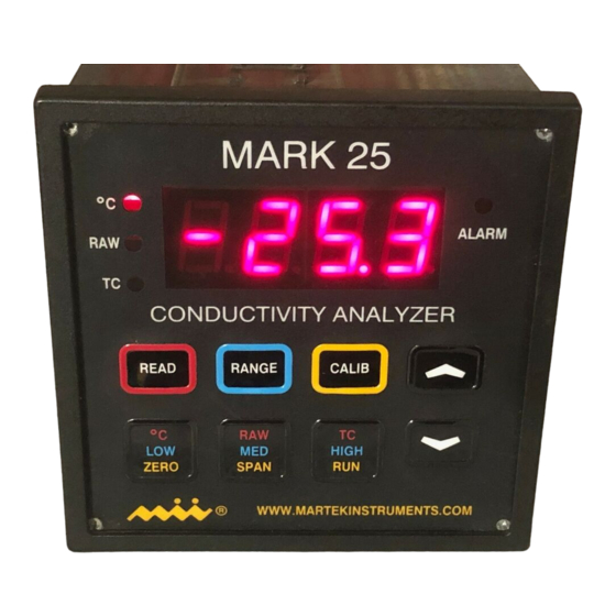
Summary of Contents for Martek Instruments Mark 25
- Page 1 Martek Instruments, Inc. Mark 25 Ultrapure Water Conductivity Analyzer Instruction Manual...
- Page 2 WARRANTY POLICY Unless otherwise stated, MARTEK INSTRUMENTS, INC. warrants this equipment to be free from defects in material and workmanship and to perform in accordance with applicable specifications for five years (one year for portable equipment) from date of shipment. All conductivity sensors are guaranteed for life.
- Page 3 MARK 25 TABLE OF CONTENTS 1. Introduction Page 1.1 Description ……………………………………………………………………………….3 1.2 Specifications ……………………………………………………………………………4 2. Installation 2.1 Panel Cutout for Monitor ..………………………………………………………………5 2.2 Sensor Dimensions …………….……………………………………………………….5 2.3 Electrical connections to the monitor ……………………………………………….…6 3. Operation 3.1 Keyboard & display ……………………………………………………………………….7 3.2 The CALIB Key...…….….…………………………………………………………………7...
-
Page 4: Description
Alarm and recorder wires are easily installed in removable terminal strips. Sensors connect via a DB-9 connector located on the rear panel of the Mark 25 and the sensors mount easily to any flat surface. In addition, Martek offers adapter plates specifically designed to cover the space occupied by other brands of conductivity analyzers. -
Page 5: Specifications
1.2 Specifications Parameter Range Accuracy Resolution 0-1.000 µS/cm +0.01 µS/cm 0.001 µS/cm Conductivity 0-10.00 µS/cm +0.1 µS/cm 0.01 µS/cm 0-100 µS/cm +1.0 µS/cm 0.1 µS/cm Temperature 0-100 +0.1 0.01 Power: 97-240 VAC, 50/60 Hz, 24Vdc, fuse protected Recorder Output: Four isolated, scaleable 0-20 mA DC analog & RS232C serial ASCII digital output Alarm Output: Four solid-state relays, 5 amp, 250 V Weight:... -
Page 6: Panel Cutout For Monitor
2. Installation 2.1 Panel Cutout for Monitor 3.60” 3.60” Panel Cut-out 2.2 Sensor Dimensions 2.75” (6.98 cm) 1.75” (4.44 cm) Side View 8.00” (20.32 cm) 1.12” (2.84 cm) Top View .125” (.31 cm) .196” (.49 cm) 2 places 4.125” (10.47 cm) -
Page 7: Electrical Connections To The Monitor
RS232 Sensors To set up the Mark 25 for operation, simply plug the sensor connector in, then plug the AC power cord into a properly grounded outlet. If recorder, digital or alarm outputs are to be used, make certain the Mark 25 is unplugged before connecting the cable to the appropriate recorder or computer. -
Page 8: Keyboard & Display
3. Operation READ key - When the <READ> key is 3.1 Keyboard and display pressed, the Mark 25 will display rd. If one of the bottom keys is selected, the The Mark 25 front panel consists of a parameter high-lighted in red will be 4 digit red LED display, 3 parameter and displayed and its corresponding LED lit. -
Page 9: Calibrating Temperature
Once the sensors have been connected to the Mark 25, the power cord can be To span temperature, press the plugged into any outlet supplying 97-240 <CALIB> key, then the <UP ARROW>... -
Page 10: Calibrating Conductivity
Aut prompt is displayed. select. The Mark 25 will display the calibration The Mark 25 will display .000 (if raw or bars then briefly display 1.000 (or 10.0 temperature-corrected conductivity is or 100.0 depending on the range... -
Page 11: Setting Recorder Outputs
To change the lower end of the recorder range, press the <ZERO> key. The NOTE: The Alarm LED will blink if there Mark 25 will display 4.00. Use the <UP> are active alarms that are not being or <DOWN ARROW> key to change the viewed and will remain steady if the number to the desired value. -
Page 12: Setting The Password
Even Word length - 7 3.8 Setting the ID Number Stop Bit - The Mark 25 can be assigned a three A communication program such as digit numeric ID number that will be PROCOMM or Microsoft HYPERLINK displayed on the digital output. -
Page 13: Setting The Auto-Ranging Function
1. Polling - The Mark 25 will provide the to activate the selection in the Mark 25’s digital output only when polled by the memory. host computer. Pressing the <RUN> key returns the 2. Periodic - The Mark 25 will Mark 25 to monitor mode.

Need help?
Do you have a question about the Mark 25 and is the answer not in the manual?
Questions and answers