Table of Contents
Advertisement
Quick Links
Advertisement
Table of Contents

Summary of Contents for Brompton Technology Tessera M2
-
Page 1: User Manual
Tessera Processor User Manual For M2, T1 and S4 processors Software Version: V1.2... - Page 2 Contents Contents Chapter 1 - Introduction Copyright Trademarks Changes About This Manual About the Tessera System Handling and Safe Operation Chapter2 - General Overview General System Overview System setup diagram Front Panel Front Panel Status LEDs Rear Panel Connections Front Panel Rear Panel Front Panel Front Panel Status LEDs...
- Page 3 Chapter 3 - Quick Start Guide Setting up your system Setting up your project Connecting your fixtures Chapter 4 - Processor Settings Processor Settings Identification Network Settings Logging Syslog Enable Watchdog Security Date and Time Fixture Firmware Preferences Auto Load Status Bar Canvas Crash Management...
- Page 4 Creating A New Project Project Management Opening and Importing Projects Deleting Projects Connecting Fixtures Cabling Connection Guidelines Adding Fixtures to a Project Adding Fixtures From Network Sub-Devices More About Topology and Associaton Swapping Fixtures and Correcting Association Changing Topology Mapping Options Interpolated Mapping 1:1 Mapping Main Project Screen...
- Page 5 Reset Reload Firmware for Selected Panels Test Pattern Selected Calibration Using the Grid Snap to Fixtures Rotating Fixtures Canvas Modes Edit Modes Video On Canvas Modes Layers Chapter 6 - Input Properties Sources SDI Inputs DVI Input Source selection Scaling and Cropping Viewport Active Area Snap Active Area to Selection...
- Page 6 Saturation RGB Shadow RGB Highlight Histograms Setting Colour Controls with the Aid of Histograms Crossfading Test Patterns Processor Test Patterns Fixture Test Patterns Beacon Chapter 7 - Colour and Brightness Intensity Gain Brightness RGB Gain Colour Temperature Gamma Chapter 8 - Presets Presets Using Masking Recording Presets...
- Page 7 Configuring the processor for Art-Net control Enabling Live Control Parameter Indicators Assign controls to a Group or Input For Fixture Groups For Input Control Minimum and Maximum Values Default Values Chapter 10 - System Management Network Load Network Bit Depth The Effect of Rotation and Interpolation on The Number of Supported Pixels Fixture Interpolation Importing Fixtures...
- Page 8 Fixture Test Patterns Beacon S4 Settings Buttons Chapter 11 - Remote Applications Tessera Remote Application Installation for Mac OS X Installation for Windows PC Network settings for Remote Management To set the IP address on a Window PC Setting the IP address in Mac OS X: Connecting to a Tessera Processor Tessera Remote Settings Disconnecting from the processor...
- Page 9 Appendices Appendix 1: Keyboard Shortcuts Appendix 2: Supported Resolutions Warranty WARRANTY CONDITIONS Index - 9 -...
-
Page 10: Chapter 1 - Introduction
Brompton Technology Ltd reserves the right to make improvements and changes to the hardware and software described in this document at any time and without notice. Brompton Technology Ltd assumes no responsibility or liability for any errors or inaccuracies that might occur in this document. About This Manual This manual provides all the information required for the correct and safe use of the Tessera processors and the supplied software. -
Page 11: About The Tessera System
For more information on becoming a Brompton partner please contact info@bromptontech.com. Handling and Safe Operation The Tessera M2 processor is packaged in a rugged custom-designed 2U 19" rackmounting case with integral mounting handles. Despite the strength of this case the processor should at all times be adequately supported in a rack. -
Page 12: Chapter2 - General Overview
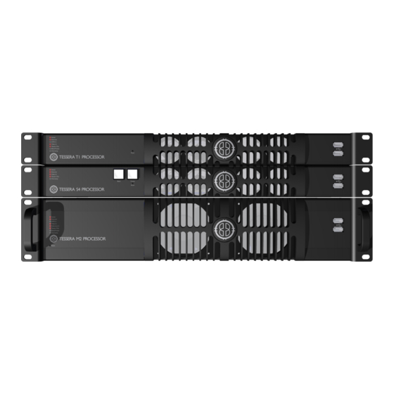
Chapter2 - General Overview General Brompton Technology make three Tessera LED video processors for different applications: M2, T1 and S4. The M2 is the flagship in the Tessera range of processors. It can control up to 2 million pixels over four Gigabit outputs and can accept incoming signals in a wide variety of formats up to and including 3G-SDI and up to 1080p60. -
Page 13: System Setup Diagram
System setup diagram Figure 2-1. Typical system set-up - 13 -... -
Page 14: Front Panel
Front Panel Front Panel Status LEDs 2 x USB2.0 type A ports, which allow for the connection of USB memory storage devices, peripherals such as keyboard or mouse or other USB devices Front Panel Status LEDs LED Name Indication Active Is lit whilst Local User Interface or Tessera Remote in use When blinking indicates that the processor is detecting a Ethernet network connection. -
Page 15: Rear Panel Connections
Rear Panel Connections M2 processor M2B processor Remote Control Connect a PC or Mac running the Tessera Remote or Tessera Control application, or an eDMX protocol directly to the local data Gigabit Ethernet port. Local User Interface The M2 Processor can be operated locally with a monitor connected via DisplayPort. Peripherals such as mouse and keyboard can be connected to the USB ports on either the front or rear panel. - Page 16 Reference Input Used for analog bi-level or tri-level sync. DMX 512-A Input For DMX real-time control. 3G-SDI Input Two 3G-SDI inputs are available. Both inputs can be used concurrently. The SDI inputs support up to 3G-SDI level A or level B. Both inputs can be used together to support Dual Link HD-SDI.
-
Page 17: Front Panel
Front Panel Front panel status LEDs Black Button: sends the output of the processor to black Freeze button: freezes the output of the processor 2 x USB 2.0 type A ports, for the connection of USB memory storage devices, peri- pherals such as a keyboard or mouse or other USB peripherals Front Panel Status LEDs LED Name Indication... -
Page 18: Rear Panel
Rear Panel Gigabit Ethernet Outputs The S4 processor has four Ethernet outputs which are provided on EtherCON connectors. Fixtures should be connected with gigabit Ethernet cable (Cat-5e or above). For more information on Ethernet connection see Connecting Fixtures on page 1. DVI-D Input A DVI-D input of up to 1920x1080 is available, with a reclocked DVI-D thru Local User Interface... -
Page 19: Front Panel
Front Panel Front panel status LEDs 2 x USB 2.0 type A ports, for the connection of USB memory storage devices, peri- pherals such as a keyboard board or a mouse or other USB peripherals Front Panel Status LEDs LED Name Indication Active Blinks whilst Local User Interface or Remote Control in use Processor is connected to Tessera Remote. -
Page 20: Tessera Control
imported to the processor via USB flash drive and connected to fixtures on the network at a later date. For details on how to install and use Tessera Remote, see "Chapter 11 - Remote Applications" on page 98 Tessera Control Tessera Control is an application available for Mac and Windows PCs that allows live control of multiple processors on the same network from one application. -
Page 21: Chapter 3 - Quick Start Guide
Chapter 3 - Quick Start Guide To get a basic system up and running, just follow these steps. This guide covers starting a new project with fixtures connected. To set up a project offline and connect fixtures at a later stage, see "Chapter 11 - Remote Applications" on page 98. Further information on all the features contained in this Quick Start Guide can be found in the relevant sections of the manual. -
Page 22: Setting Up Your Project
Figure 3-2. The Start Screen Setting up your project 5. From the Start Screen, select New… The New Project Wizard will launch. Figure 3-3. The New Project Wizard 6. Type in a name for your project. If you are using Tessera Remote in offline mode, you can also select the location in which it is to be saved (if you are accessing the processor directly, the project will be saved to its internal storage). -
Page 23: Connecting Your Fixtures
tiple fixtures. 8. Click Create. You will now be taken to the Main Project Screen. Figure 3-4. Main Project Screen Connecting your fixtures Figure 3-5. Add fixture from network button Click the Add Fixtures From Network button. The Add Fixtures From Network toolbar will be displayed. - Page 24 Figure 3-6. The Add Fixtures From Network toolbar. 1. The processor will show any attached strings of fixtures and the number of fixtures on each string. In the picture above, the processor can see fixtures connected to outputs 1, 2 and 3. Outputs 1 and 2 have a single string of 9 fixtures on each output, whilst Out- put 3 has 4 strings with 12, 18, 24, and 12 fixtures.
-
Page 25: Chapter 4 - Processor Settings
Chapter 4 - Processor Settings From the Main Project Screen it is possible to set a number of user definable settings for the processor. In the Main Project Screen choose Settings from the Tools menu. Figure 4-1. Tools dropdown menu Processor Settings Figure 4-2. -
Page 26: Network Settings
processors. If no name is set the processor will be displayed by its serial number in the Discovered Processors list in Tessera Remote. Network Settings The default IP address of a Tessera processors is 192.168.0.50 with subnet mask of 255.255.255.0. In addition to being able to set the processor to different static addresses and ranges it is also possible to set processors to receive an IP address from a DHCP server. -
Page 27: Security
Security Figure 4-3. Security settings with no password set- the default setting. Figure 4-4. Setting a password It is possible to set a password for the processor. This password will then be requested from users connecting to the processor from the Tessera Remote application. The password is reset if factory settings are restored or it can be removed by re-entering the password in this window. -
Page 28: Fixture Firmware
Fixture Firmware Figure 4-6. Fixture Firmware screen This window allows you see which version of fixture firmware is currently set as the preferred for each type of supported fixture. Typically this will be the firmware version included with that version of processor software. Should you wish to set the processor to upload a different version of fixture firmware which was not included with the release software of the processor it is possible to load newer (and older) versions of fixture firmware and assign these as the default for a particular fixture. -
Page 29: Preferences
Note. This window does not load firmware to any fixtures. It simply sets the preferred file to be used if you do decide to reload firmware from this processor. For more information on fixture firmware and the options for reloading see Reload Fixture Firmware Preferences Figure 4-7. -
Page 30: Canvas
operations are undertaken. It provides keyboard shortcut information and tips to aid the user. If you wish to turn this off you can uncheck this option. Canvas This section contains settings to help with selecting and aligning fixtures on the canvas. These features are explained in "Using the Grid"... -
Page 31: Reload Firmware
Format internal storage will overwrite the memory of the processor. This will wipe all project files from the memory of the processor and also any imported fixture definition files and fixture firmware not included in the current software release. The current software version of the processor will be retained after an internal storage format has been performed. -
Page 32: Processor Status
Processor Status Figure 4-12. Processor status window The processor status window gives a significant amount of useful information on the current setup and the condition of the processor. This ranges from details of the current software and hardware setup to data about the temperature, network settings and revision numbers of particular components in the processor. - Page 33 software, the company address and the support email address: support@bromptontech.com - 33 -...
-
Page 34: Chapter 5 - Project Setup
Chapter 5 - Project Setup Creating A New Project Figure 5-1. The New Project Window The New Project Wizard is launched each time you start a new project on the processor, Tessera Remote or the Offline Editor. 1. To start a new project, click New… in the Start Screen or in the Project menu in the Main Project Screen. - Page 35 USB flash drive or an other USB storage device you will need to export it. See "Project Management" on the next page If you are creating a project with only one fixture type: 1. Select the manufacturer and fixture type from the dropdown menus. 2.
-
Page 36: Project Management
Figure 5-2. Selecting a canvas size from the Advanced View 2. In the advanced mode, you do not have the option of automatically generating an array of fixtures - the fixture types you have selected will be available in the library once the project has been created. -
Page 37: Deleting Projects
Connecting Fixtures Cabling The Brompton Tessera M2 processor can drive any Tessera compatible LED panel, mesh or batten system. Most panel products will have a panel controller card fitted inside each cabinet or tile. In the case of ray or batten type products where there is a low pixel count per fixture, the panel controller card may be housed in a buffer box and a number of fixtures connected to each buffer. -
Page 38: Connection Guidelines
The processor communicates with LED fixtures on the network using the Tessera protocol, which is transmitted via cabling that conforms to Cat 5e or above (this includes Neutrik etherCON terminations). The topology of a Tessera system is very simple. The fixtures just need to be connected to the processor either directly or via a Gigabit Ethernet network switch. -
Page 39: Adding Fixtures To A Project
Adding Fixtures to a Project The diagram below shows a typical system setup with some strings connected directly from the processor and some via a network switch. Each differently coloured group of panels represents one of the strings in the screenshot in the previous section. The red and green strings are connected directly to output ports 1 and 2 of the processor. -
Page 40: Adding Fixtures From Network
Adding Fixtures From Network Once the fixtures are physically connected to the network, the processor will auto-detect them (provided the fixture types were selected when the project was created) and the Add Fixtures From Network toolbar ("Add Fixtures From Network toolbar. " below) will turn green. -
Page 41: Sub-Devices
Sub-Devices Sub-devices are fixtures that have a smaller pixel count than traditional LED panels, and often have a different shape or format, such as LED strips. Sub-devices are connected to special controller boxes called Root Nodes which supply power and data to the Sub-devices and are sometimes referred to as PDU or Power and Data Units. - Page 42 Figure 5-8. A Root Node with unassociated Sub-devices To configure connected Root Nodes: select the relevant Root Node you wish to configure so that it is highlighted. Note that Sub-devices can be shown or hidden by selecting the Show Sub-devices button. Click on the Configure button to open the Configure Root Node dialog box.
-
Page 43: More About Topology And Associaton
It is worth noting the system will limit the number of sub-devices according the maximum supported capacity of the Root Node. Please see the manufacturers documentation for further details on configuring specific Sub- devices. Figure 5-10. Associated Sub-devices More About Topology and Associaton The Tessera system uses the unique MAC address of each fixture to identify the order of the fixtures. -
Page 44: Changing Topology
1. Disconnect and remove the faulty fixture or controller box. 2. Insert and connect a good fixture into the same position in the string.The processor will prompt with: Figure 5-11. The correct association dialog box 3. This message will be on screen for 10 seconds. After this time you can find the Correct Association option by right clicking on the icon of the affected fixture or by selecting Correct Association from the Edit menu. - Page 45 Figure 5-13. Second venue topology. To correct a screen follow the following steps: 1. On the canvas select all the panels that have the wrong topology. Right click on one of the panels and select Disassociate. 2. Now click the Edit Topology button to view the Topology toolbar and select the string of fixtures you wish to correct by double clicking on the dot in the centre of one of the panels.
- Page 46 second panel on the string. A dotted red line will be drawn which will go solid as the line becomes pinned to the centre spot of the next panel in the string. You can now move on to the third fixture in the string and so forth until the string is complete. Figure 5-15.
-
Page 47: Mapping Options
Alternatively you can display the Add Fixtures from Network toolbar to see the unassociated fixtures icon highlighted with a colour. Click on this icon and then click on the first fixture in the string to associate the fixtures. Now click on the green arrow to come out of the Add Fixtures from Network toolbar and the fixtures will associate and come online. -
Page 48: Main Project Screen
Main Project Screen Figure 5-18. Main Project Screen 1. Drop-down menus 2. Left Toolbar: Undo and Redo Zoom In and Out Add Fixtures Add Fixtures from Network Change Topology Record Preset 3. Source Previews 4. Processor Name/ Processor serial number 5. -
Page 49: Moving Around The Canvas
Moving Around the Canvas Up and down vertical scrollbar arrow keys page up/down keys mouse wheel Left and right horizontal scrollbar arrow keys shift + mouse wheel Zoom in and out mouse wheel + Ctrl Hold the space bar and left click + drag the Drag the canvas mouse Fixture Layout... -
Page 50: Grouping Fixtures
selection area to Overlaps selection area. If 'Inside selection area' is enabled, the line must completely enclose fixtures in order to select them. If 'overlaps selection area' is enabled, a fixture will be selected if any part of it falls within the selection area. Grouping Fixtures If there are several fixtures in your configuration that you always want to move and adjust together, it may be helpful to put them into a group. -
Page 51: Beacon
Beacon The Beacon button highlights selected fixtures by using the Identify test pattern which features a white border with a dark blue on each of the selected fixtures. The status LEDs will also flash on the back of the selected fixtures. Figure 5-20. -
Page 52: Test Pattern
Test Pattern The Test Pattern drop-down menu allows you to select a range of internal test patterns that are generated on the fixtures themselves. These patterns are particularly useful for testing a range of fixture and fixture module based issues. Figure 5-21. -
Page 53: Snap To Fixtures
The grid can be displayed by right-clicking on the canvas in the Main Project Screen and toggling Show Grid in the context menu. Snap to Grid can be enabled in the same way. These options can also be accessed in Tools > Settings > Preferences. Selecting Properties from this right-click menu, displays grid colour and spacing options in the Properties tab on the right-hand side of the screen when the canvas itself is selected. - Page 54 Edit Mode: (keyboard shortcut F1) Edit Mode is the default mode for the canvas and allows fixture positioning. In Edit mode the fixtures are displayed as viewed from the front. Rear Edit Mode: (keyboard shortcut F2) Fixtures are commonly cabled up from behind and Rear Edit allows fixtures on the canvas to be horizontally flipped, as if viewed from behind.
-
Page 55: Video On Canvas Modes
Figure 5-24. Rear Edit Mode Video On Canvas Modes Video on Canvas modes allows the display of the currently selected video input, taking into account Viewport and Active Area settings. Video on Canvas Modes are not available on Tessera Remote. Fixtures cannot be moved on the canvas whilst in Video on Canvas Modes. Fixture Only Mode: (keyboard shortcut F3) Fixture only mode displays the currently selected video input as it is being displayed on the... - Page 56 Figure 5-25. Fixture Only Mode Video and Fixture Mode: (keyboard shortcut F4) Video and Fixture Mode displays the currently selected video input on both the fixtures and the canvas. The video within the Active Area that is not being displayed on the fixtures is shown greyed out as shown in the picture below.
- Page 57 Figure 5-26. Video and Fixture Mode Video Only Mode: (keyboard shortcut F5) Video Mode displays the currently selected video input within the Active Area on the canvas without displaying the fixtures. - 57 -...
- Page 58 Figure 5-27. Video Mode Figure 5-28. Video Mode with scaled input - 58 -...
-
Page 59: Layers
Layers Figure 5-29. The Layers tab Layers are an easy way of manipulating overlapping fixtures. Fixtures can be assigned to layers which have a z-order. Z-order refers to the front to back ordering. Assigning panels to layers that make tasks such as On Screen Calibration (OSCA) and other fixture based adjustments easier. -
Page 60: Chapter 6 - Input Properties
HDMI can be supported by use of a suitable adapter, however, the Tessera processors does not support HDCP. Source selection The three video inputs on the Tessera M2 processor are mapped to two input pipelines to allow crossfading between sources. - 60 -... -
Page 61: Scaling And Cropping
Any of the inputs may be used as a reference signal for genlock (See section "Genlock Settings" on page 92). Scaling and Cropping The Tessera M2 processor achieves scaling and cropping of the incoming feed by use of three settings in the input tab: Viewport, Zoom and Active Area. Viewport The Viewport settings define the region of interest of the incoming feed which is captured to the canvas. -
Page 62: Active Area
Figure 6-2. Incoming 1920x1080 video at its original size. If however you wish to capture only part of that incoming feed (perhaps because you then wish to expand the image to fill the canvas) you can set these values accordingly. For example, if you wished to capture a window of PAL content being displayed towards the bottom right corner of an HD feed you might set the Viewport to: Figure 6-3. - Page 63 Figure 6-4. The Geometry Tab Figure 6-5. The canvas with the Active Area shown by a dashed border. Having determined the region of interest to be captured from the incoming feed using the Viewport, that region can then be sized or moved to the appropriate part of the canvas. To set the Active Area to the same dimensions as the Viewport click the Snap to Viewport button.
-
Page 64: Snap Active Area To Selection
Snap Active Area to Selection To automatically size the incoming image to fit on a particular group of fixtures, select the chosen fixtures and click the Snap to Selection button The Active Area will then be sized and positioned to fit over the selected fixtures. 4:3 and 16:9 The 4:3 and 16:9 buttons will automatically adjust the width parameter of the Active Area to the chosen ratio based on the height. -
Page 65: Input Colour Control
The aspect ratio of the Viewport is maintained with the Fill image scaled to fill the active area. The image is scaled to the exact dimensions of the active Stretch area without maintaining aspect ratio. Input Colour Control Black Level The black level control affects the base level of brightness of the darkest content in the incoming feed. -
Page 66: Rgb Shadow
brightness information intact or boost its colour to give a more colourful (perhaps too colourful) image. RGB Shadow In addition to being able to set a black level for a given input it is also possible to set the black level specifically for each of the primary colours in that input. These sliders, called RGB Shadow, equate to a setting for the black level of each specific colour. - Page 67 Figure 6-6. Test pattern showing colour bars at 75% and the corresponding Linear RGB histogram. The above picture shows a test pattern and its corresponding Linear RGB histogram. Note that there are clear columns at 75% for each of the three primaries. This is because all of the colours are either primary colours at 75% (red, green and blue sections) or secondary colours made from combinations of the primaries at 75% (cyan, yellow, magenta and white sections).
-
Page 68: Setting Colour Controls With The Aid Of Histograms
The fact that the peaks corresponding to the black and white areas of the input image are located at the very start and end of each histogram indicates that this content source is well balanced and the full spectrum is being used. Setting Colour Controls with the Aid of Histograms The histograms can be useful in determining if a particular incoming signal is filling the entire spectrum of colour and brightness. - Page 69 Figure 6-10. Adjusting the contrast control will make brighter areas appear closer to the 100% threshold, assuming you have some areas of white content in your image and this is desirable. If specific colours do not appear to be rendering correctly you may wish to adjust the RGB Highlight and Shadow controls to work on that specific colour without affecting the other two primaries.
-
Page 70: Crossfading
Crossfading Crossfading between inputs is achieved by storing the different inputs as presets with a crossfade time. To store presets to crossfade from one input to another follow these steps: 1. Select the input you wish to create a preset for (all tiles will change to this input). 2. -
Page 71: Fixture Test Patterns
To turn off test patterns click on the icon again and it will turn grey. To change test pattern click on the small white triangle to the right of the icon and it will give a selection of test patterns as shown in figure X. Custom Test Patterns allows custom test pattern bitmaps to be loaded into the processor. - Page 72 The beacon button can be found towards the bottom of the Properties tab. It will highlight the panel in solid blue with a white border around the edge. If the panel is equipped with status LEDs these will flash yellow allowing easy recognition from the rear also. - 72 -...
-
Page 73: Chapter 7 - Colour And Brightness
Chapter 7 - Colour and Brightness There are four ways to modify the colour and brightness of fixtures connected to the Tessera system. Global colour - the controls on the Colour tab will affect all fixtures connected to the processor. Global Colour controls are located on the Colour tab to the right of the Main Project Screen. -
Page 74: Rgb Gain
value of the slider will be the value of the brightest fixture in the project, so in this example it would be 5000 Nits. Tip: If you wish to control the brightness of an array including different types of fixtures whilst maintaining them at a matching level then this is best achieved by leaving the brightness slider at default and modifying the intensity slider. - Page 75 Figure 7-1. Global Colour Override It is possible to remove single fixtures or groups of fixtures from the control of the Global Colour sliders and assign values to them separately. This functionality may be useful if you wish to maintain one whole screen at a constant brightness when there are fixtures grouped into separate screens on a processor.
-
Page 76: Chapter 8 - Presets
Chapter 8 - Presets Presets Presets are a way of storing the settings that you make on the processor so that they can be recalled quickly and easily. These presets can be made to affect all the panels or a small selection of them depending on how they are grouped. -
Page 77: Using Masking
Video information - the parameters contained in the inputs tab including the selected input source, the colour and brightness information for each input and the geometry information (Viewport and Active Area). Pressing one of the Record Preset buttons opens the Preset Recording view. Using Masking Figure 8-2. -
Page 78: Recording Presets
Recording Presets Before storing a Position preset it is necessary to combine the panels you want to be controlled into a group (see "Fixture Layout" on page 49). Note: A group can consist of a single panel. To record a preset: 1. -
Page 79: Using Presets To Crossfade Between Inputs
Right-click on a preset recall button to rename or delete it. Using Presets to Crossfade Between Inputs Switching inputs can be achieved by creating a Video (V) preset for each input. This is a feature only available on M-Series processors. To assign crossfade times to these presets right click on each preset and select properties. -
Page 80: Chapter 9 - Live Control
Chapter 9 - Live Control Introduction Live Control allows users to control and modify the colour, video and position parameters of the processor remotely using DMX or the DMX over Ethernet protocol Art-Net. These are parameters which would normally be controlled either by adjusting sliders, selecting options from drop down menus, or in the case of panel position by dragging icons in the graphic user interface (GUI) of the processor or its remote software. -
Page 81: Configuring The Processor For Dmx Control
Control Profile – A control profile contains information about the parameters and assignable items that can be controlled when using that Control Profile and maps these to particular channels. Figure 9-2. Choosing Protocol and Control Profile Protocol – Denotes the actual Control Protocol which is being used to control the processor. This can be DMX (via the 5 pin XLR input) , Art-Net (via a network connection), or the Tessera Control protocol which allows control of multiple processors from one application. -
Page 82: Configuring The Processor For Art-Net Control
M2B processors can be identified by a serial number that starts with 002xxx. Configuring the processor for Art-Net control 1) Connect an Art-Net source to the Net, Net 1 or Net 2 port on the processor’s back panel (either directly or via switch). 2) Go to the Live Control tab and select Art-Net from the Control Protocol drop down menu. - Page 83 Figure 9-4. Live Control Tab and icon Live control can be enabled by checking the box marked Enable Controls or by clicking on the live control icon. The icon will appear blue when Live Control is enabled. Once Live Control is enabled any parameters included in a selected Control Profile will go to the value defined by the incoming DMX or Art-Net signal.
-
Page 84: Parameter Indicators
Figure 9-7. Configured and enabled but not receiving Signal A control profile has been chosen and Live control is now enabled. No valid control protocol signal is being received at this point so the faders will default to either the last valid signal received or the GUI values before Live control was enabled. ... - Page 85 Figure 9-10. Control profile configured with Live Control active Figure 9-11. Control profile configured and Live Control disabled. A selection of Control Profiles that can be used to control various parameters are included in the processor. These profiles are intended to cover the majority of use cases. However where necessary it is possible to modify and create new Control Profiles to suit a particular application. ...
-
Page 86: Assign Controls To A Group Or Input
1x Channel to trigger up to 127 user definable presets. Input Controls - (30 channels total if fully assigned) 3x Assignable controls of Input Colour management parameters. Input Controls+ - (36 channels total if fully assigned) 1x Global control of Red, Green, Blue and Intensity Gain. 3x Assignable controls of Input Colour management parameters. -
Page 87: For Input Control
Figure 9-12. Configuring Fixtures Figure 9-13. Configuring Fixture Groups In the illustration above the example project includes 4 fixture groups that have been renamed to describe the screens they control. The user can then assign each screen to set of DMX channels and parameters that are controllable their DMX or Art Net control device. -
Page 88: Minimum And Maximum Values
Minimum and Maximum Values Minimum and Maximum values are contained within Control Profiles that set the range of parameter values that can be achieved when controlled with Live Control. This includes being able to set lower and upper limits. This is useful in situations where it may be important to limit the lower or higher values of a parameter. -
Page 89: Chapter 10 - System Management
Chapter 10 - System Management Network Load Figure 10-1. The Network Load bars The network section of the Systems Tab is a graphical representation of the network load on each Tessera Protocol output. The greater the network load on an output, the further to the right the green bar will be. -
Page 90: The Effect Of Rotation And Interpolation On The Number Of Supported Pixels
The table below illustrates the relationship between bit depth, network refresh rate and network bit depth. Refresh/ Bit Depth 8 bit 10 bit 12 bit 24 Hz 1,250,000 1,000,000 833,333 25 Hz 1,200,000 960,000 800,000 30 Hz 1,000,000 800,000 666,666 50Hz 600,000 480,000... -
Page 91: Importing Fixtures
Note When importing new fixture types it is important to ensure that they are compatible with the installed version of firmware if not included. Please contact Brompton Technology if you are unsure or experience trouble importing new fixture types to a processor. -
Page 92: Genlock Settings
Genlock Settings Figure 10-4. Genlock Settings Internal The internal setting allows an overall refresh rate for the processor to work at, which can be 23.98, 24, 25, 29.97, 30, 50, 59.94 and 60 fps, irrespective of the frame rate of sources coming in to the processor. -
Page 93: Custom Test Patterns
Figure 10-5. Additional Video Delay Additional video delay allows the output refresh to be delayed by up to 5 frames. This allows Tessera processors to match the latency present in other display systems. Custom Test Patterns It is possible to import a bitmap to use as custom test pattern. To use the custom test pattern select the test pattern button on the main canvas window and select Custom Test Pattern from the drop down menu. -
Page 94: Test Patterns
For interlaced sources the latency is 2 fields for constant current fixtures and 3 fields for PWM driver fixtures. When fixtures that use constant current drivers are mixed with PWM fixtures then the processor adds a frame of latency on to the constant current driver fixtures to match the latency of the PWM fixtures. -
Page 95: Fixture Test Patterns
To turn off test patterns click on the icon again and it will turn grey. To change test pattern click on the small white triangle to the right of the icon and it will give a selection of test patterns as shown in figure X. Custom Test Patterns allows custom test pattern bitmaps to be loaded into the processor. -
Page 96: S4 Settings
The beacon button can be found towards the bottom of the Properties tab. It will highlight the panel in solid blue with a white border around the edge. If the panel is equipped with status LEDs these will flash yellow allowing easy recognition from the rear also. S4 Settings Figure 10-7. - Page 97 Figure 10-8. S4 buttons on the front panel The buttons illuminate red when they are activated. The Black button causes the connected fixtures to be blacked out. The Freeze button causes the video signal being displayed on the fixtures to be frozen. The Freeze button can also be customised to show a custom test pattern/ bitmap instead of it's Freeze function.
-
Page 98: Chapter 11 - Remote Applications
Tessera processors across a network. Additionally the Remote application can be used as an ‘offline editor’, allowing the set up and editing of Tessera projects when away from a physical processor. Tessera Remote is downloadable from the Brompton Technology website: http://bromptontech.com/support#downloads Installation for Mac OS X 1. - Page 99 4. The setup wizard will then ask you for a location. - 99 -...
-
Page 100: Network Settings For Remote Management
5. When the application has finished installing then you should see the completion dialog box. Click Finish to finish the installation process. Network settings for Remote Management To connect to a Tessera processor you must connect your Mac or Windows PC to a Tessera processor’s remote network interface via an Ethernet network. - Page 101 with. - 101 -...
- Page 102 2. Select Properties. This will open the network adapter properties. 3. Double click on Internet Protocol Version 4 (TCP/IPv4). This will allow you do set an IP address. 4. Click on Use the following IP address to manually enter an IP address. Given that the default IP address of a Tessera processor is 192.168.0.50/ 255.255.255.0, choose an IP address that isn’t already taken with in the 192.168.0.x range, where x is a number - 102 -...
-
Page 103: Setting The Ip Address In Mac Os X
between 1 and 254, except for 50. 5. Click OK. Your computer should now be ready to connect to a Tessera processor. Setting the IP address in Mac OS X: More recent Mac laptops have been shipped from Apple without a wired Ethernet network interface. -
Page 104: Connecting To A Tessera Processor
Connecting to a Tessera Processor Having physically connected the processor to an Ethernet network with a Tessera processor on, launch the Tessera Remote application. This will open a dialogue box that allows the user to select whether to start the Remote Application in Remote mode or in Offline Editor mode. -
Page 105: Tessera Remote Settings
If the version of Tessera Remote and the processor firmware are not the same, then you may update the processor firmware to match the version of Tessera Remote you are using across the network directly from Tessera Remote. To do this select the processor on which you wish to reload the firmware, and click Reload Processor Firmware. -
Page 106: Multiple Processor Control
When you launch Tessera Remote in Offline Editor mode you are presented with the Offline Editor menu that allows you to select a recent project or open a recent project, as well as set canvas settings. If there are existing projects already saved on your Windows PC or Mac then these will be listed on the Offline Editor Recent Projects Menu. - Page 107 Figure 11-1. Windows PC side by side application instance Figure 11-2. Alt-Tab allows the user to select the relevant instance. Figure 11-3. In Mac OS ⌘ -Tab to select the relevant instance. - 107 -...
-
Page 108: Tessera Control
Tessera Control Figure 11-4. Control application GUI The Tessera Control application is used to control commonly used parameters such as: screen brightness, contrast and black level and RGB gain; source selection, test patterns, freeze and blackout across a number of processors Processors can be grouped into 'channels' to allow different groups of processors to be controlled from within one application. - Page 109 Figure 11-5. Selecting the Tessera control protocol The Enable Controls check box or the Live Control button must be selected. To configure the Control Application, the relevant Network Interface should be selected from the drop down menu on the user interface. Then select the relevant control channel group you wish to control.
-
Page 110: Chapter 12 - On-Screen Colour Adjustment
Chapter 12 - On-Screen Colour Adjustment On-Screen Colour Adjustment (OSCA) Tessera processors feature comprehensive fixture-based seam adjustment for fixture and module seams and 7 way colour correction for modules and panels. High pixel pitch fixtures require absolute mechanical precision when connecting to adjacent panels. - Page 111 Figure 11-6. Putting the processor into OSCA Mode via the Tools menu. Putting the processor into OSCA Mode will disable the video output. Figure 11-7. The disable video output warning OSCA adjustments are performed in the On-Screen Colour Adjustment window. Figure 11-8. The On-Screen Colour Adjustment window - 111 -...
-
Page 112: Display Colour
The On-Screen Colour Adjustment window displays the fixtures in the project as they are positioned on the canvas and has a toolbar that is particular to fixture colour and luminance adjustments. Fixtures can be selected the same way as on the Project Screen. Layers can be particularly helpful with selecting panels for OSCA adjustment. -
Page 113: Seam Adjustment
OSCA works in one of two modes: Seam Adjustment, which allows the luminance adjustment of fixtures and fixture modules, or Colour Adjustment which allows colour adjustment of fixtures or fixture modules. Seam Adjustment Seam adjustments allow the correction of luminance at the seams at the edges of fixtures or between adjacent modules within fixtures. - Page 114 Figure 11-12. OSCA on fixtures showing selected seams and cursor Once the desired seams have been selected then the luminance can be adjusted by clicking and dragging up or down on the Seam Adjustment Luminance thumbwheel. You can also hover the mouse pointer over the Luminance thumbwheel and use the scroll wheel on your mouse.
- Page 115 Figure 11-13. Seam Brightness Correction panel. The Seam Brightness Control panel features Layer selection. See "Layers" on page 59 for more information on Layers. Displayed Layers have a tick along side them. To 'hide' layers then click on the tickbox to untick the box on layers you wish to hide. Hidden layers do not output OSCA Mode.
-
Page 116: Colour Adjustment
Colour Adjustment Colour Adjustment allows powerful 7 way colour correction of fixtures or fixture modules, but with a quick and intuitive user interface. To access Colour Adjustment of fixtures then select the Fixture icon on the OSCA toolbar or press F8, and to adjust modules select the Modules icon on the OSCA toolbar or press F7 Figure 11-14. - Page 117 Figure 11-15. The canvas showing module selection mode for Colour Adjustment - 117 -...
- Page 118 Figure 11-16. The canvas in fixture selection mode for Colour Adjustment Modules or fixtures can be selected in the usual manner, depending on whether you have Module or Fixture Colour Adjustment selected. When the required fixtures or modules have been selected, the Colour Adjustment panel is displayed. The Colour Adjustment panel is similar in nature to the Seam Brightness Control panel.
- Page 119 Figure 11-17. The Colour Adjustment panel showing Master Colour Controls and White Adjustments The Colour Adjustment panel features Master Colour Controls: Luminance, Red Gain, Green Gain and Blue Gain. These give an overall level of colour control. In a similar fashion to adjusting Seam Luminance values, these values can be changed in a few different ways: moving the mouse pointer over to the required parameter thumbwheel and clicking and dragging up and down, or clicking and using the scroll wheel, or by using the keyboard...
- Page 120 By using the the Display Colour controls Colour Adjustments can be made to white and primary and secondary colours. NB The controls only adjust the colour of the test pattern being used. Selecting White from Display Colours allows Luminance, Red, Green and Blue Gain to be adjusted for white.
-
Page 121: Osca Keyboard Shortcuts
Selecting red, green, blue, cyan, magenta or yellow from Display Colour allows Hue, Saturation and Luminance to be adjusted for each respective colour. The Hue, Saturation and Luminance can be adjusted in much the same way as above. The keyboard shortcuts for Hue, Saturation and Luminance are Q, W and E respectively. - Page 122 Ctrl+Space Change Display Colour backwards OSCA Colour and Luminace Adjustments Luminance Adjustment Red Gain Green Gain Blue Gain increase/ decrease parameter Click+Scroll Wheel Decrease parameter Increase parameter Ctrl+ parameter shortcut Fine Adjustment White Adjustment Luminance Adjustment Red Gain Green Gain Blue Gain Red, Green, Blue, Cyan, Magenta and Yellow Adjustment Hue Adjustment Saturation Adjustment...
-
Page 123: Appendices
Appendices Appendix 1: Keyboard Shortcuts Global Undo Ctrl+Z Ctrl+Shift+Z or Redo Ctrl+Y Delete or Back- Delete selected fixtures or groups space End current task Escape Show properties for selected fixtures or groups (or for canvas if Ctrl+I there is no selection) While moving a slider, Don't snap to default value hold Alt... -
Page 124: Appendix 2: Supported Resolutions
Invert snapping behaviour Ctrl++ Zoom In Ctrl+- Zoom Out Ctrl+0 Zoom 1:1 Ctrl+wheel Zoom in and out Middle-click and drag Zoom to the dragged rectangle Space+drag Pan the view Appendix 2: Supported Resolutions Tessera M2 Supported Resolution/Framerate List - 124 -... - Page 125 Horizontal Vertical Supported Frame Supported Name Scan Type Active Active Rates Input/s NTSC (480i) Interlaced 59.94Hz NTSC (16:9) Interlaced 59.94Hz 720x480p Progressive 59.94Hz 720x480p Progressive 59.94Hz (16:9) PAL (576i) Interlaced 50Hz PAL (16:9) Interlaced 50Hz 720x576p Progressive 50Hz 720x576p Progressive 50Hz (16:9) 640x480...
- Page 126 Progressive 23.98, 24, 25, 1920x1080PsF 1920 1080 Segmented 29.97, 30Hz Frame - 126 -...
-
Page 127: Warranty
Warranty Brompton Technology Limited (”Brompton”) warrants that its Products will be free from defects in materials and workmanship for a period of two (2) years (”Warranty Period”) from the original date of purchase and that any spare parts will be free from defects in materials and workmanship until the end of the Warranty Period or 3 months from the date of which they have been incorporated into the Product, whichever is the later. ... - Page 128 4. Damage caused by lightning, water, fire, acts of God, war, public disturbances, incor- rect mains voltage, improper ventilation or any other cause beyond the control of Brompton. 7. This warranty is valid for any person who legally acquired possession of the Product during the warranty period.
-
Page 129: Index
Index Active Area 62 Adding Fixtures to a Project 39 Adding Fixtures From Network 40 Additional Video Delay 92 Art-Net Control 82 Beacon 71, 95 Black Level 65 Cabling 37 Canvas Modes 53 Edit Mode 54 Reverse Edit Mode 54 Changing Aspect Ratio 64 Changing Topology 44 Colour Adjustment 116... - Page 130 Creating a New Project 34 Crossfading Inputs 70, 79 Custom Test Patterns 93 Date 27 Deleting Projects 37 DMX Control 81 DVI Input 60 Editing Presets 78 Fixture Firmware 28 Fixture Layout 49 Fixture Test Patterns 71, 95 Gamma 74 Genlock 92 Genlock Source 92 Internal 92...
- Page 131 HDCP 60 HDMI 60 Histograms 66 Hue 65 Identification 25 Importing A Project 36 Input Colour Control 65 Installing Remote Application 98 Installing for Mac OS X 98 Installing for Windows PC 98 Intensity Gain 73 Layer 59 Live Control 80 Logging 26 Low Latency Mode 93 Mapping Options 47...
- Page 132 Moving Fixtures 50 Multiple Processor Control 106 Network Load 89 Network Settings 26 Offline Editor 105 On-Screen Colour Adjustment (OSCA) 110 Opening A Project 36 OSCA Keyboard Shortcuts 121 Preferences 29 Auto Load 29 Canvas Settings 30 Crash Management Settings 30 Format Internal Storage 30 Processor Status 32 Reload Firmware 31...
- Page 133 Recording Presets 78 Remote Application 98 Remote Network Settings 100 Mac Network Settings 103 PC Network Settings 100 Remote Settings 105 RGB Gain 74 RGB Highlight 66 RGB Shadow 66 Root Nodes 41 Rotating Fixtures 53 Saturation 65 Scaling and Cropping 61 Screen Brightness 73 SDI Input 60 Seam Adjustment 113...
- Page 134 Supported Resolutions 124 Swapping Fixtures 43 Syslog 26 System Overview 12 Tessera Remote 19 Test Patterns 70, 94 Time 27 Video On Canvas Modes 55 Fixture Only Mode 55 Video and Fixture Mode 56 Video Only Mode 57 Viewport 61 Warranty 127 Watchdog 26 Zoom 64...
Need help?
Do you have a question about the Tessera M2 and is the answer not in the manual?
Questions and answers