Table of Contents
Advertisement
Advertisement
Table of Contents

Summary of Contents for Hermes VANGUARD OPTIMA
- Page 1 VANGUARD OPTIMA USER’S MANUAL...
- Page 3 VANGUARD OPTIMA Laser Engraving and Cutting System User’s Guide Manufactured by: Universal Laser Systems, Inc. 16008 North 81st Street Scottsdale, AZ 85260 Phone: 480-483-1214 Fax: 480-483-5620 August 1998...
- Page 4 Notice This publication and its contents are proprietary to Universal Laser Systems, Inc. (ULS), and are intended solely for the contractual use of ULS, Inc. customers. While reasonable efforts have been made to assure the accuracy of this manual, ULS shall not be liable for errors contained herein or for incidental or consequential damage in connection with the furnishing, performance, or use of this material.
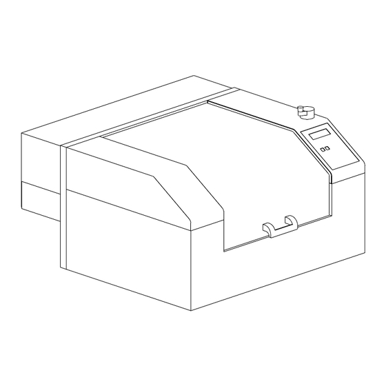
- Page 5 Introduction Thank you for purchasing the Vanguard Optima Laser System. Being the first desktop laser engraving and cutting system ever created, the Optima stands out among the crowd. It has been designed to combine flexibility and full featured performance without sacrificing simplicity, ease of use, and ease of maintenance.
- Page 7 Contents SECTION 1 - Safety .................1-1 General Safety..................1-1 Laser Safety.................... 1-2 Laser Safety Labels ................1-3 Other Safety Labels ................1-6 FCC Compliance ..................1-7 EU Compliance (CE) ................1-8 SECTION 2 - Installation ................2-1 Operating Environment................2-1 Electrical Requirements................
- Page 8 Bitmapped / Scanned Images..............4-4 Encapsulated Postscript (EPS) Images ..........4-6 Postscript (PS) Images ................4-6 SECTION 5 - System Operation .............5-1 How it Works................... 5-1 The Control Panel................... 5-4 The Menu System................... 5-7 Menu Descriptions ................5-10 Focusing ....................5-22 SECTION 6 - Running the System Step by Step ......6-1 Powering Up ...................
- Page 9 Brass - Coated..................8-8 Corian / Avonite / Fountainhead ............. 8-9 Cork ...................... 8-10 Delrin (Seal Press)................8-11 Glass / Crystal ..................8-12 Leather ....................8-13 Marble....................8-14 Mat Board ..................... 8-15 Melamine ....................8-16 Melamine - Photo / Clipart Engraving ........... 8-17 Plastic - Engravers Microsurfaced ............
-
Page 10: Section 1 - Safety
SECTION 1 Safety This section describes hazards that may occur if the laser system is installed or used improperly. Failure to follow these guidelines can result in injury to yourself, others, or may cause severe damage to the equipment. Use, misuse, or abuse of the equipment in a manner other than what is described in this manual may increase this risk. -
Page 11: Laser Safety
Safety The laser system is specifically designed to comply with CDRH performance • requirements under 21 CFR 1040.10 and 1040.11. CDRH is the Center for the Devices of Radiological Health division of the Food and Drug Administration (FDA). This laser system also complies with CE (European Community) safety regulations. -
Page 12: Laser Safety Labels
Safety Do not modify or disable any safety feature of this system. Do not operate any system that has had its safety features modified, disabled, or removed. Improper use of controls and adjustments, or performance of procedures other than those specified in this manual, may invalidate the safety of this system. - Page 13 Safety Locations (2): One is on the top door and visible under normal operation. The other is located inside the laser system on the back panel, visible when the top door is opened. Locations (3): One is next to the Beam Window where the laser beam enters the engraving area inside the laser system and is visible when the top door is opened.
-
Page 14: Other Safety Labels
Safety D A N G E R CAUTION LASER RADIATION LASER RADIATION - AVOID DO NOT STARE INTO BEAM OR VIEW DIRECT EYE EXPOSURE DIRECTLY WITH OPTICAL INSTRUMENTS CLASS 3A LASER PRODUCT LASER DIODE LASER DIODE WAVELENGTH: 630-680 nm WAVELENGTH: 630-680 nm MAX. - Page 15 Safety Locations (2): One is on the back of the laser system’s cooling fan cover. Visible from the outside under normal operating conditions when viewed from the backside of the system. The other is on the plastic shield over the back of the power entry module. INPUT POWER: INPUT POWER: 110 VAC;...
-
Page 16: Fcc Compliance
Safety FCC Compliance This ULS laser system has been tested and found to comply with Federal Communication Commission (FCC) directives regarding Electromagnetic Compatibility (EMC). In accordance with these directives ULS is required to provide the following information to its customers. FCC Compliance Statement and Warnings This device Complied with FCC Rules Part 15. -
Page 17: Eu Compliance (Ce)
Safety EU Compliance (CE) EU Declaration of Conformity LASER SYSTEMS Product Identification: Optima Laser Cutting and Engraving System Manufacturer: Universal Laser Systems, Inc. 16008 N. 81 Scottsdale, AZ 85260 Universal Laser Systems, Inc. hereby declares that the equipment specified below is in conformity with the following directives: 89/336/EEC (EMC Directive) 73/23/EEC... -
Page 18: Section 2 - Installation
SECTION 2 Installation Proper operating conditions are vital to a safe and productive environment. From choosing the right location to plugging in the connectors, this section describes the ideal environment and setup of the laser system. Operating Environment Please follow the guidelines below. Failure to provide the proper operating environment for the can cause damage to the laser system as well as your computer. -
Page 19: Electrical Requirements
Installation Electrical Requirements This system has the above electrical rating. Make sure that your electrical outlet is capable of providing the proper voltage, frequency and amperage that this system requires. Noisy or unstable electricity as well as voltage spikes can cause interference with the electronics of the laser system. -
Page 20: Exhaust Requirements
Installation Exhaust Requirements To properly exhaust fumes and smoke from the laser engraving system during operation, it is necessary to provide an exhaust unit moving a minimum of 200 CFM (cubic feet per minute) at 6 inches of static pressure (inches of water). Please refer to the sample diagram on the next page. - Page 21 Installation...
-
Page 22: Unpacking And Assembling The System
Installation Unpacking and Assembling the System Since packaging can change from time to time, please refer to the Unpacking and Assembly Instructions found inside of the shipping container when you first opened it. Computer Requirements The following is our minimum recommended computer configuration. Using a faster computer with more capacity will increase efficiency and throughput. -
Page 23: Font Requirements
Installation CAD Software AutoCAD for Windows • AutoCAD LT for Windows • Autosketch for Windows • DesignCAD for Windows • CAD users do not necessarily need Windows or Windows compatible programs. The laser system is compatible with any program that can output standard HPGL commands whether it is Windows based or not. -
Page 24: Making The Connections
Installation Making the Connections Never connect or disconnect the printer cable while either the computer or the laser system is powered ON. Always power down both units when connecting or disconnecting the printer cable. Please use the parallel cable supplied with the system. It is a 6 foot high quality shielded cable that has a molded ferrite choke built in. - Page 25 Installation Never connect the laser system through a manual switch type A/B switch box. connecting an additional laser system or other printer to the same computer, we recommend the installation of an additional parallel port into the computer.. This creates electrical noise which can cause an engraving problem or can damage the laser system and/or the computer’s electronics.
-
Page 26: Section 3 - The Printer Driver
SECTION 3 The Printer Driver This section describes how the computer controls the laser system through the printer driver. It defines some very important terms that you need to know in order to operate the system correctly so please read it thoroughly. How the Computer Controls the Laser System The laser system is a unique type of output device. -
Page 27: Installing The Windows 95 Printer Driver
16. Select “No” when it asks to print a test page, and then click on “Finish”. 17. Click once on “Vanguard Optima” then click on “File” and drag the mouse to “Properties”. 18. The driver settings screen will appear. Click on the different tabs to get familiar with all of the controls. -
Page 28: Driver Controls
The Printer Driver Driver Controls The Vanguard Optima Printer Driver for Windows 95 (driver for short) has the appearance of other Windows 95 printer drivers. A thorough understanding of how Windows 95 operates is essential to operating the drivers controls. Please refer to your Windows 95 manual or online help screen on how to install, operate, and troubleshoot Windows 95. - Page 29 The Printer Driver Power Setting Laser power is controlled by assigning the percentage of power from 0 - 100% to each color used in the graphic drawing. Since the laser is proportionally pulsed, this percentage represents how long the laser remains on for each laser pulse fired. Basically, the power setting is directly related to how deep the engraving will be.
- Page 30 ON. Clipart mode also provides greater compatibility with Windows software that do not work well with vector devices such as the Vanguard Optima laser system. Save A unique feature of the driver is being able to store all of the driver’...
- Page 31 The Printer Driver Engraving Field Tab Start Options If you would like the laser system to start engraving without having to push the “Start” button on the control panel, select the “Auto Start” button. In order for this option to work, the laser system must be set to the “One File Memory”...
- Page 32 The Printer Driver Orientation The laser system has two modes of orientation, “Landscape” and “Portrait” mode. Landscape mode is the normal mode of operation. As indicated by the arrows, the landscape mode causes the laser system to raster in the left and right direction. The Portrait mode causes the laser system to raster from the front to the back of the laser system.
- Page 33 The Printer Driver Dither Type Specifies the type of dithering used in printing non-black and white bitmaps and multicolored clipart images. Since the laser system is really acts like a black and white printer (laser ON is considered black and laser OFF is considered white), grayscale or color photographs(bitmaps), as well as multicolored clipart images get turned into dithered images when reproduced by the laser system.
- Page 34 The Printer Driver The “Error Diffusion” method should work in all software programs available because its pattern is entirely created by the driver. However the “Halftone” methods pattern is partially created by the driver and partially created by the software program you are using. If your software program does not support this type of printing, then the image will look like a solid black and white image without any dot pattern at all.
- Page 35 3-10 The Printer Driver 3D Effects This option enables the laser system to raster engrave materials in a three dimensional fashion where the image appears to be “chiseled” or “sunken”. The beam appears to have engraved the material on an angle but in actuality it is a precise control of laser power that creates this appearance.
- Page 36 The Printer Driver 3-11 Print as a Mirror Image Mirrors the ENTIRE PAGE from left to right(horizontally). Will not mirror individual objects or selections. Very useful for doing rubber stamps because the objects that are on screen are readable, but when they engrave, they come out mirrored. Shoulder Choose from one of the preset options by clicking the down arrow in the “Shoulder Type”...
- Page 37 3-12 The Printer Driver The above settings are just an example to show you how to use the controls. This example might not achieve the exact stated results on your particular material. This is why the driver has custom settings available for you to control. Delete Custom Shoulder Click on the custom shoulder that you want to delete and then click on this button to permanently delete it.
-
Page 38: Section 4 - Graphics Software
SECTION 4 Graphics Software Choosing the right graphics software program to run the laser system is essential for maximum usage and control of the laser system. Not all software can be used to run the laser system because many have limitations. Because you may be using a word processing software to output to your laser printer does not mean you should use it to output to your laser engraving system. - Page 39 Graphics Software It is also possible to use a page size smaller than the maximum engraving area. For example, if an 8 inch(203.2 mm) x 10 inch(254 mm) page size is desired, set this page size in the graphics software as well as in the driver. The laser system will automatically move the engraving area to the origin so place the object all the way up into the left hand corner against the rulers in the laser system.
- Page 40 Graphics Software 4-3 The printer driver will interpret these objects as vectors and will cut them out providing that your software has the capability of vector output. Basically, all software programs have the ability to provide raster output. However, not all programs have the ability to provide vector output even if you set the line width to the smallest thickness possible.
-
Page 41: Speed Optimizing
Graphics Software Overlapping Outlines The driver does not filter outlines that overlap each other. If placing one outline one on top of another, both outlines will be cut by the laser system. This is a useful feature that will allow deeper cutting by passing the laser over a single outline path twice or more. - Page 42 Graphics Software There are several different bitmap storage formats available: TIF, BMP, PCX, and others. We prefer to use the TIFF format because it is most widely used format. The format makes no difference to the laser system. The difference in formats involves how they are stored on your computers hard disk.
-
Page 43: Encapsulated Postscript (Eps) Images
Graphics Software Encapsulated Postscript (EPS) Images Bitmap images cannot be cut by the laser system only engraved. The only way to have the laser system cut out or vector a bitmap is to first convert it to a vector file format such as an EPS. -
Page 44: Section 5 - System Operation
SECTION 5 System Operation In this section you will learn how the laser system actually works and familiarize you with laser system terminology. You will then start working with the control panel and learn how to get around in the menu system. Since there are many features in this laser system, the menu system may seem complicated at first, but once you start using it, you will find out that it is a very simple system to operate. - Page 45 System Operation Laser Tube Assembly The laser tube assembly is a very sophisticated device. It is composed of a plasma tube filled with a special mixture of CO2 and other gases, and RF (radio frequency) electronics. The function of the entire assembly is to turn electrical energy into concentrated light energy. The word LASER is an acronym for Light Amplified Stimulated Emission of Radiation.
- Page 46 System Operation size that would prohibit the engraving of fine detail. This can be related to trying to write small text with a wide, felt tip marker. There are pros and cons to the different lenses that are available for different applications. Please refer to the Appendices section on available lenses and their operating characteristics.
-
Page 47: The Control Panel
System Operation The Control Panel The control panel on the laser system provides easy access to all of the controls necessary for cutting and engraving operations. The control panel consists of a liquid crystal display (LCD), indicator lights, and selection buttons. The following section will describe, in detail, how to maneuver through the menu system and the significance of each item in the control panel. - Page 48 System Operation DO NOT download files until the display reads “READY” as this can lead to an incorrect or corrupted file download. Corrupted file downloads can lead to an incorrect firing of the laser which can destroy the material you are engraving. The two up and down arrow buttons to the left and below the LCD give complete access to the menu control system.
- Page 49 System Operation Red Indicator Light CONDITION REASON The laser system is initializing The laser system is firing the beam in the Alignment Mode The laser system has finished initializing and is ready to receive a file The top door is closed FLASHING The top door is open The Process Controls...
-
Page 50: The Menu System
System Operation Pressing and holding down an arrow button will cause the focus lens assembly to move in the respective direction. The motion system starts off slowly, but if you continue to hold down the button, you will see it accelerate to a faster speed. Pushing the button once and letting it go quickly will move the motion system in .001 inch increments. - Page 51 System Operation...
- Page 52 System Operation...
-
Page 53: Menu Descriptions
5-10 System Operation Menu Descriptions The remainder of this section will describe each one of the menus and their significance. READY Menu When the system is first powered on “INITIALIZING” will appear for approximately 30 seconds until the laser system finishes performing its routine. When the system has finished initializing, “READY”... - Page 54 System Operation 5-11 The first line indicates the filename. If more than one job has been downloaded, you can move to the next file in memory by pressing the “NEXT FILE” button. You can page through the list of files available in memory by placing the cursor on the first line of this display and pressing the “SELECT”...
- Page 55 5-12 System Operation Secondly, when using DOS based programs, a printer driver other than the Windows printer driver must be used. DOS printer drivers do not know to send the required EOF to the laser system after file downloading. Again, the memory buffer will not recognize any file that exists if it does not have an EOF.
- Page 56 System Operation 5-13 The file name displayed is always the currently active file and there are two methods for looking through the list of files to choose another one. The first method is to press the “NEXT FILE” button on the control panel. Each time the “NEXT FILE” button is pressed, the next file in memory becomes the current file.
- Page 57 5-14 System Operation DOS POWER SETTINGS Menu The laser system allows eight different power settings to be saved, in non-volatile(permanent) memory, and used when processing a DOS based file. Since DOS based printer/plotter drivers do not have the ability to set the “POWER”, “SPEED”, and “PPI” settings, the settings must be set manually on the laser system.
- Page 58 System Operation 5-15 CONFIGURATION Menu Selecting this menu will allow the reconfiguration of certain features of the engraving system and will lead to other menu items. ONE FILE MEMORY Menu Pressing “SELECT” key while cursor is on this line will toggle the setting on and off. When off, it enables the multiple file memory buffer system (default).
- Page 59 5-16 System Operation SET ROTARY AXIS Menu The Rotary Fixture Axis is a setting that is pre-set at the factory. The laser system will sense when the Rotary Fixture is plugged in and will position the X-Axis arm directly over the centerline of rotation automatically when it begins to engrave.
- Page 60 System Operation 5-17 ALIGNMENT MODE Menu This menu allows access to firing the laser beam manually to determine if the laser systems optical alignment is correct. The factory setting is a very low power setting that is just strong enough to check the laser beam alignment. Please refer to the maintenance section on how to safely check the laser systems beam alignment.
- Page 61 5-18 System Operation In order to use the “SERIAL” port, the communication settings MUST match those of the computer. Refer to the computers hardware and software manuals for details on setting up the computers serial port. If using the “SERIAL” port, select the fastest possible “BAUD” rate for communication since this effects how quickly the computer can send files to the laser system.
- Page 62 System Operation 5-19 SET FOCUS POSITION Menu This option allows you to set the focus position to anywhere in the field that you desire. Normally, the factory default setting for the “Z SETUP” button is (1,1). If you would like to change the factory default setting, go to this menu and press the “SELECT”...
- Page 63 5-20 System Operation MEMORY TEST Menu It may be necessary to use the diagnostic tests if instructed to do so by a member of our technical support staff. The “MEMORY TEST” is a memory buffer test to test the RAM in the laser system.
- Page 64 System Operation 5-21 ABOUT Menu Use the up and down arrow buttons to position the cursor on this menu item. Press the “SELECT” button and our copyright notice along with the current versions of firmware will be displayed. The firmware version numbers are a diagnostic aid to our service technicians. If you are having a problem with the laser system, a technician might ask you to read out the numbers in this display.
-
Page 65: Focusing
5-22 System Operation Setting a new origin other than the default (0,0) position will shrink your field size. If you already have files already loaded into memory that utilize the entire engraving area, and you set a new origin, part of that graphic might fall out of the effective printing area. If you run this file, unexpected results can occur that might destroy your material in the engraving area. - Page 66 System Operation 5-23 Now, using the Z-axis adjustment knob, move the table either up or down so that the flat side of the tool can sit flat up against the side of the focus carriage. Slowly raise the table until you observe the tool either tilting or sliding away from the focus carriage.
-
Page 67: Section 6 - Running The System Step By Step
SECTION 6 Running the System Step by Step In this section we will cover how to completely use the laser system to create a product from start to finish. From powering on everything to removing the finished product from the system, we will cover the entire process step by step. -
Page 68: Focusing Methods
Running the System Step by Step Focusing Methods Before attempting to adjust the focal height, first make sure that the table is down low enough to prevent the focus carriage from hitting into the piece of wood. To adjust the table height, use the Z-axis adjustment knob. -
Page 69: Creating The Graphic
Running the System Step by Step WARNING: DO NOT engrave or cut too far out of focus as this can be a potential fire hazard. A maximum of two (2) complete turns of the Z-axis adjustment knob in either direction from precise focus should be the limit. It does not matter whether you bring the table up to go out of focus, or down, the effect is the same. - Page 70 Running the System Step by Step Once the printer driver is visible, click on the appropriate tabs and duplicate the drivers properties as the diagrams below illustrate:...
-
Page 71: Downloading The File
Running the System Step by Step Downloading the File You are now ready to print to the laser system. Make sure the laser system is powered on and the display reads “ READY”. Find the “PRINT” command within your graphics program and click on it. Depending on which graphics program you are using, the menu command “PRINT”... -
Page 72: Material Removing And Reloading
Running the System Step by Step We will also remind you again to please follow the below warning label. Material Removing and Reloading Once the laser system has completed processing you material, the laser beam will turn off, the motion system will move to its home position in the upper right hand corner, the system will beep twice, and the green light on the control panel will glow continuously. -
Page 73: Section 7 - Accessories
SECTION 7 Accessories There are two accessories available for this laser system, the Rotary Fixture and 3D Effects. The Rotary Fixture controls in the printer driver are used along with the optional Rotary Fixture to engrave onto round or cylindrical objects. The 3D effects can be used to create rubber stamps or produce a 3D effect on other materials. - Page 74 Accessories Single Stamp Method To create the artwork and engrave only one or a few stamps, set the page size in the graphics program to something smaller than the full field. Just as an example, we will use a page size that is 8.5 x 11 inches (215.9 x 292.1 mm) in the Landscape mode.
- Page 75 Accessories 7-3 Place the sheet of rubber into the upper left hand corner against the rulers, as the following diagram illustrates, and be sure to properly focus on the material. Set the printer driver properties as shown below. These settings came from the section on Sample Materials. There is a considerable difference between rubber blends, thickness, and hardness between different manufacturers.
- Page 76 Accessories Also set the following in the printer driver. As you can see, we set the page size in the driver equal to the graphics programs page size. We also selected "ADD SHOULDER”, “NORMAL RUBBER STAMP”, and “PRINT AS MIRROR IMAGE”.
- Page 77 Accessories 7-5 If desired, output the page to a paper printer for proofreading. Printing out a positive image to a printer is easier to read and uses less toner or ink than a negative print. In the laser systems printer driver, use the same settings as the previous example but with only one modification.
-
Page 78: Section 8 - Sample Materials
SECTION 8 Sample Materials This section provides driver settings and helpful hints to get started engraving and/or cutting various materials. These settings are to serve as a starting point and are not necessarily optimized for each particular application. Safety NEVER LEAVE THE SYSTEM RUNNING UNATTENDED FOR ANY REASON. Exposure to the laser beam can cause ignition of combustible materials. - Page 79 Sample Materials DO NOT ENGRAVE OR CUT PVC (Polyvinylchloride) BASED MATERIALS. The fumes are extremely toxic if you inhale them. The fumes are so caustic that it can chemically destroy the metal parts of the laser system. Damage to the laser system from this type of abuse WILL NOT be covered under warranty.
-
Page 80: Acrylic - Cast And Extruded
Sample Materials ACRYLIC - CAST AND EXTRUDED TYPE POWER SPEED PASS DEPTH LIGHT RASTER ENGRAVING .001” COMMENTS: Remove original factory masking from the engraving surface. Leave the masking on the non- engraved surface to prevent accidental scratches. TYPE POWER SPEED PASS DEPTH DEEP RASTER ENGRAVING... - Page 81 Sample Materials ADDITIONAL COMMENTS There are two types of acrylic available, cast and extruded. Cast turns white or frosted and extruded remains clear when engraved. Use extruded acrylic for paint filled engraving and cast for regular engraving. Cast engraves better without masking. Lightly engrave the surface to frost it with a low power setting such as the first setting listed above.
-
Page 82: Acrylic - Mirrored
Sample Materials ACRYLIC - MIRRORED TYPE POWER SPEED PASS DEPTH LIGHT RASTER ENGRAVING .003” COMMENTS: Engrave unmasked and on the backside in reverse text. Engraving on the front side of mirrored acrylic will visually produce a double image. TYPE POWER SPEED PASS DEPTH... - Page 83 Sample Materials ADDITIONAL COMMENTS Engraving mirrored acrylic is similar to engraving regular acrylic. The idea is to engrave through the mirrored backing enough to begin to penetrate into the acrylic. Engraving deeply will cause, a crusty residue to form just like with non-mirrored acrylic. A double image will appear if engraving on the front side of the mirror.
-
Page 84: Anodized Aluminum
Sample Materials ANODIZED ALUMINUM TYPE POWER SPEED PASS DEPTH RASTER ENGRAVING .001” COMMENTS: The power required is dependent on the thickness of the anodized coating. Do not overpower because the anodized will either be dull in appearance or the engraving lines will be too thick. -
Page 85: Brass - Coated
Sample Materials BRASS - COATED TYPE POWER SPEED PASS DEPTH RASTER ENGRAVING 1000 .002” COMMENTS: Engrave unmasked. Use a light setting to engrave through the coating. Using 1000 PPI seems to have a cleaner removal of the coating. Some thicker coated brass will require more power. -
Page 86: Corian / Avonite / Fountainhead
Sample Materials CORIAN / AVONITE / FOUNTAINHEAD TYPE POWER SPEED PASS DEPTH RASTER ENGRAVING .005” COMMENTS: Mask first before engraving if planning to paint fill. TYPE POWER SPEED PASS DEPTH DEEP RASTER ENGRAVING .015” COMMENTS: Mask first if planning to paint fill. TYPE POWER SPEED... -
Page 87: Cork
8-10 Sample Materials CORK TYPE POWER SPEED PASS DEPTH RASTER ENGRAVING .010” COMMENTS: Engraved unmasked. TYPE POWER SPEED PASS DEPTH VECTOR ENGRAVING .010” COMMENTS: Engrave unmasked. TYPE POWER SPEED PASS DEPTH VECTOR CUTTING .060” COMMENTS: Unmasked. A low PPI setting is used to prevent flaming. ADDITIONAL COMMENTS Cork is not very popular for engraving but it does engrave and cut nicely. -
Page 88: Delrin (Seal Press)
Sample Materials 8-11 DELRIN (SEAL PRESS) TYPE POWER SPEED PASS DEPTH RASTER ENGRAVING .015” COMMENTS: Engraved unmasked. TYPE POWER SPEED PASS DEPTH VECTOR CUTTING .060” COMMENTS: Unmasked. A low PPI setting is used to prevent flaming. ADDITIONAL COMMENTS Making a seal using plastic is revolutionizing the industry. The laser can engrave and cut out a typical Notary Seal in less than 5 minutes. -
Page 89: Glass / Crystal
8-12 Sample Materials GLASS / CRYSTAL TYPE POWER SPEED PASS DEPTH RASTER ENGRAVING .001” COMMENTS: Since glass will not vaporize when laser engraving, it does not require a lot of laser power. TYPE POWER SPEED PASS DEPTH VECTOR ENGRAVING .001” COMMENTS: Again, since glass will not vaporize, it does not require much laser power. -
Page 90: Leather
Sample Materials 8-13 LEATHER TYPE POWER SPEED PASS DEPTH LIGHT RASTER ENGRAVING .001” COMMENTS: Engrave unmasked. TYPE POWER SPEED PASS DEPTH DEEP RASTER ENGRAVING .010” COMMENTS: Engrave unmasked. Deeper engraving will require masking to prevent smoke damage. TYPE POWER SPEED PASS DEPTH VECTOR ENGRAVING... -
Page 91: Marble
8-14 Sample Materials MARBLE TYPE POWER SPEED PASS DEPTH RASTER ENGRAVING .003” COMMENTS: Engrave unmasked. Too much laser power by running too slowly will engrave too deep and discolor. TYPE POWER SPEED PASS DEPTH VECTOR ENGRAVING .003” COMMENTS: Engrave unmasked. ADDITIONAL COMMENTS Most marble and polished stones will turn white when engraved. -
Page 92: Mat Board
Sample Materials 8-15 MAT BOARD TYPE POWER SPEED PASS DEPTH RASTER ENGRAVING .005” COMMENTS: Engrave unmasked. A low PPI setting is used to prevent discoloration. TYPE POWER SPEED PASS DEPTH VECTOR ENGRAVING .005” COMMENTS: Engrave unmasked and at a low PPI setting. TYPE POWER SPEED... -
Page 93: Melamine
8-16 Sample Materials MELAMINE - STANDARD ENGRAVING TYPE POWER SPEED PASS DEPTH RASTER ENGRAVING .015” COMMENTS: Engrave unmasked. TYPE POWER SPEED PASS DEPTH DEEP RASTER ENGRAVING .020” COMMENTS: Engrave unmasked. TYPE POWER SPEED PASS DEPTH VECTOR ENGRAVING .010” COMMENTS: Engrave unmasked. ADDITIONAL COMMENTS Engraving melamine is very similar to engraving regular wood with the added benefit of a consistent surface finish and uniform base material composition. -
Page 94: Melamine - Photo / Clipart Engraving
Sample Materials 8-17 MELAMINE - PHOTO/CLIPART ENGRAVING TYPE POWER SPEED PASS DEPTH RASTER ENGRAVING .008” COMMENTS: Engrave unmasked. Use a resolution of 500 DPI. TYPE POWER SPEED PASS DEPTH RASTER ENGRAVING .008” COMMENTS: Engrave unmasked. Use a resolution of 250 DPI. ADDITIONAL COMMENTS Engraving photographs can be challenging at first but becomes easier once there is an understanding of what to look for and how to achieve the desired results. -
Page 95: Plastic - Engravers Microsurfaced
8-18 Sample Materials PLASTIC - ENGRAVERS MICROSURFACED TYPE POWER SPEED PASS DEPTH RASTER ENGRAVING .003” COMMENTS: Remove original masking and leave unmasked. Use enough power to remove the surface material and expose the underlying substrate. TYPE POWER SPEED PASS DEPTH DEEP RASTER ENGRAVING .015”... - Page 96 Sample Materials 8-19 RUBBER STAMPS TYPE POWER SPEED PASS DEPTH RASTER ENGRAVING .030” COMMENTS: Different blends and densities of rubber will engrave to different depths. Test the rubber first to determine the correct power settings. TYPE POWER SPEED PASS DEPTH VECTOR CUTTING .040”...
-
Page 97: Sign Vinyl
8-20 Sample Materials SIGN VINYL TYPE POWER SPEED PASS DEPTH RASTER ENGRAVING .015” COMMENTS: These parameters are for engraving vinyl on wood. Apply the vinyl to the wood and squeegee out air bubbles. Mask with transfer tape. Engrave deep enough to go through the tape, vinyl, and into the wood. - Page 98 Sample Materials 8-21 WOOD TYPE POWER SPEED PASS DEPTH RASTER ENGRAVING .020” COMMENTS: Engrave unmasked. If masking, reduce the speed setting to 50% to get the same depth. TYPE POWER SPEED PASS DEPTH VECTOR ENGRAVING .030” COMMENTS: Engrave unmasked. TYPE POWER SPEED PASS...
- Page 99 8-22 Sample Materials pieces will fall through to the table when cutting is finished. If raising the wood, set up the drawing so that the inner pieces of the drawing are cut first, otherwise pieces may fall through at the wrong time. Not all wood finishes are created equal.
-
Page 100: Section 9 - Maintenance
SECTION 9 Maintenance Keeping the laser system clean will ensure the highest quality engraving. The frequency of cleaning will depend entirely on the type of material being engraved, the performance of your exhaust blower, the operating environment, and the amount of laser system usage over a given period of time. - Page 101 Maintenance...
-
Page 102: System Cleaning
Maintenance 9-3 System Cleaning Turn off and unplug the laser system. • Open the Top Door and thoroughly remove all loose dirt and debris from inside the machine • with a vacuum cleaner. Clean the Engraving Table surface with either soap solution, alcohol, or acetone, and paper •... - Page 103 Maintenance #2 Mirror To gain access to the #2 Mirror, the mirror cover must be removed. Remove the thumbscrew, slide the cover to the right slightly and lift straight up. Inspect the #2 Mirror and clean it only if there is debris present. There are two ways to clean the mirror, with a moistened cotton swab or a moistened lens tissue.
- Page 104 Maintenance 9-5 #3 Mirror and Focus Lens You must remove the front cover to the Focus Carriage to gain access to the #3 Mirror and the Focus Lens. To do this, hold the front cover with one hand and with the other hand, remove the three(3) thumbscrews that attach the front cover to the Focus Carriage, and pull the front cover straight out.
-
Page 105: Adjustments And Lubrication
Maintenance Beam Window The Beam Window is where the laser beam enters into the engraving area. It is located in the upper left hand corner of the engraving area against the back wall and is yellow in color. It is not necessary to remove the Beam Window for cleaning since it can only get dirty on the front side. -
Page 106: Maintenance Schedule
Maintenance 9-7 Battery Replacement CAUTION There is a danger of explosion if the battery is incorrectly replaced. Replace the battery only with the same or equivalent type recommended battery manufacturer. Using an incorrect battery, recharging or disassembling the battery may present a danger due to fire or explosion. - Page 107 Appendix A - Warranty Please insert your warranty statement here.
- Page 108 Appendix B - Vanguard Optima Specifications Model Number Vanguard Optima Maximum Engraving Area 18 x 12 inches (457.2 x 304.8 mm) Maximum Engraving Speed 25 inches per second (635 mm/s) Laser Source LX25 C02 Laser Tube Laser Beam Spot Size Diameter 1.5 inch Focal Length (optional)
- Page 109 Appendix C - Using DOS Based Programs DOS software is not standardized and each application will work differently. When using DOS applications, it is not possible to print through the Windows Printer Driver and for this situation, the system has been designed to automatically emulate a Hewlett Packard plotter. Plotters use a special language called HPGL which the laser system has been designed to accept.
- Page 110 Appendix D - Using Macintosh Computers The laser system has primarily been designed to run under the Windows 95 operating system. Since there has been a high demand for Macintosh users, we have created a Macintosh based printer driver. If you ordered the Macintosh printer driver and the special printer cable required, please refer to the installation and operation instructions included with your order.
- Page 111 Appendix E - Serial Port Cable Requirements...
- Page 112 Appendix F - Software Anomalies In order for certain software to work properly with your laser system, some modifications might have to be made. If using the following software, be sure to follow these instructions. If having any difficulty making these adjustments, please contact our technical support. CorelDraw If experiencing problems printing text in CorelDraw!, especially mirrored text,...
- Page 113 COREL 5.0 Find the CORELAPP.INI file usually located in the c:\corel50\config\ subdirectory. Open this file up in a text editor such as NOTEPAD, which comes with Windows. Scroll down about 64 lines to find the line that reads: FontRasterizer=1 and change it to read: FontRasterizer=0 Save this file and restart CorelDraw! for the changes to take effect.
Need help?
Do you have a question about the VANGUARD OPTIMA and is the answer not in the manual?
Questions and answers