Table of Contents
Advertisement
5700 - SERVICE
SERIAL NUMBER RECORD
SERIAL NUMBER RECORD
Record serial numbers and date of purchase in spaces provided.
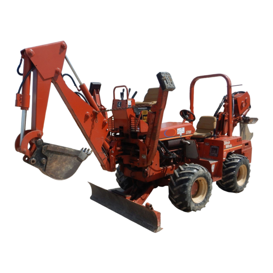
Tractor serial number is located as shown.
Date of Manufacture:
Date of Purchase:
Tractor Serial Number:
Engine Serial Number:
1
SERVICE
5700 - SERVICE
SERIAL NUMBER RECORD
SERIAL NUMBER RECORD
Record serial numbers and date of purchase in spaces provided.
Tractor serial number is located as shown.
Date of Manufacture:
Date of Purchase:
Tractor Serial Number:
Engine Serial Number:
1
SERVICE
Advertisement
Table of Contents

Summary of Contents for Dutch Witch 5700
- Page 1 5700 - SERVICE 5700 - SERVICE SERIAL NUMBER RECORD SERIAL NUMBER RECORD SERVICE SERVICE SERIAL NUMBER RECORD SERIAL NUMBER RECORD Record serial numbers and date of purchase in spaces provided. Record serial numbers and date of purchase in spaces provided.
-
Page 2: Support Procedure
5700 - SERVICE 5700 - SERVICE SUPPORT PROCEDURE SUPPORT PROCEDURE SUPPORT PROCEDURE SUPPORT PROCEDURE Notify your dealer immediately of any malfunction or failure of Notify your dealer immediately of any malfunction or failure of Ditch Witch equipment. Ditch Witch equipment. -
Page 3: Foreword
5700 - FOREWORD 5700 - FOREWORD FOREWORD FOREWORD This manual is an important part of your equipment. It provides This manual is an important part of your equipment. It provides safety information and operation instructions to help you use and safety information and operation instructions to help you use and maintain your Ditch Witch equipment. - Page 4 5700 - FOREWORD 5700 - FOREWORD Operator's Manual Operator's Manual 5700/Z5700 5700/Z5700 Issue No. 3.0/OP-2/04 Issue No. 3.0/OP-2/04 Part Number 054-519 Part Number 054-519 Copyright 1998, 1999, 2000, 2001, 2003, 2004 Copyright 1998, 1999, 2000, 2001, 2003, 2004 by The Charles Machine Works, Inc., by The Charles Machine Works, Inc.,...
- Page 5 5700 - CONTENTS 5700 - CONTENTS CONTENTS CONTENTS SERVICE ......... . 1 SERVICE .
- Page 6 5700 - CONTENTS 5700 - CONTENTS TRACTOR ........43 TRACTOR .
- Page 7 5700 - CONTENTS 5700 - CONTENTS SAW ATTACHMENT ....... 75 SAW ATTACHMENT .
- Page 8 5700 Tractor ....... . .131 5700 Tractor ....... . . 131 H514 Trenching Attachment .
-
Page 9: Overview
5. Engine compartment 6. Backfill blade (optional) 6. Backfill blade (optional) The 5700 is a four-wheel drive, hydrostatic tractor that can be The 5700 is a four-wheel drive, hydrostatic tractor that can be fitted with a wide variety of digging attachments including fitted with a wide variety of digging attachments including vibratory plows, saws, trenchers, backhoes, and drilling units. - Page 10 5700 - OVERVIEW 5700 - OVERVIEW The H412 trencher cuts trenches up to 52" (1.3 m) and a The H412 trencher cuts trenches up to 52" (1.3 m) and a maximum of 12" (300 mm) wide. Hydraulic traverse allows the maximum of 12"...
-
Page 11: Controls
5700 - CONTROLS 5700 - CONTROLS CENTER CONSOLE OVERVIEWS CENTER CONSOLE OVERVIEWS CONTROLS CONTROLS CENTER CONSOLE OVERVIEWS CENTER CONSOLE OVERVIEWS 5700 5700 1. Fuel gauge 1. Fuel gauge 2. Hydraulic oil temperature indicator 2. Hydraulic oil temperature indicator 3. Engine oil temperature indicator 3. - Page 12 5700 - CONTROLS 5700 - CONTROLS CENTER CONSOLE OVERVIEWS CENTER CONSOLE OVERVIEWS Z5700 Z5700 1. Fuel gauge 1. Fuel gauge 2. Tachometer 2. Tachometer 3. Oil pressure gauge 3. Oil pressure gauge 4. Hydraulic oil temperature indicator 4. Hydraulic oil temperature indicator 5.
-
Page 13: Center Console Descriptions
5700 - CONTROLS 5700 - CONTROLS CENTER CONSOLE DESCRIPTIONS CENTER CONSOLE DESCRIPTIONS CENTER CONSOLE DESCRIPTIONS CENTER CONSOLE DESCRIPTIONS Fuel Gauge Fuel Gauge This gauge indicates fuel level in This gauge indicates fuel level in tank. Use only diesel fuel. tank. Use only diesel fuel. - Page 14 5700 - CONTROLS 5700 - CONTROLS CENTER CONSOLE DESCRIPTIONS CENTER CONSOLE DESCRIPTIONS Engine Oil Temperature Indicator Engine Oil Temperature Indicator This indicator lights and engine This indicator lights and engine shuts down when engine oil shuts down when engine oil temperature is high.
- Page 15 5700 - CONTROLS 5700 - CONTROLS CENTER CONSOLE DESCRIPTIONS CENTER CONSOLE DESCRIPTIONS Ignition Switch Ignition Switch This switch is used to start engine. This switch is used to start engine. • Insert key and turn it • Insert key and turn it clockwise to start position.
- Page 16 5700 - CONTROLS 5700 - CONTROLS CENTER CONSOLE DESCRIPTIONS CENTER CONSOLE DESCRIPTIONS Ground Drive Foot Control Ground Drive Foot Control This pedal controls forward and This pedal controls forward and backward tractor movement. backward tractor movement. • Press front of pedal to speed •...
- Page 17 5700 - CONTROLS 5700 - CONTROLS CENTER CONSOLE DESCRIPTIONS CENTER CONSOLE DESCRIPTIONS Voltmeter Voltmeter This gauge measures voltage in This gauge measures voltage in electric system. Reading should be electric system. Reading should be near 14 volts with engine running.
- Page 18 5700 - CONTROLS 5700 - CONTROLS CENTER CONSOLE DESCRIPTIONS CENTER CONSOLE DESCRIPTIONS Oil Pressure Gauge (Z5700 only) Oil Pressure Gauge (Z5700 only) This gauge shows oil pressure. This gauge shows oil pressure. Normal operating pressure is Normal operating pressure is 30-100 psi (2-6.9 bar).
-
Page 19: Right Side Control Overviews
5700 - CONTROLS 5700 - CONTROLS RIGHT SIDE CONTROL OVERVIEWS RIGHT SIDE CONTROL OVERVIEWS RIGHT SIDE CONTROL OVERVIEWS RIGHT SIDE CONTROL OVERVIEWS 5700 5700 1. Ground drive speed/direction 1. Ground drive speed/direction control (orange) control (orange) 2. Backfill blade control 2. -
Page 20: Right Side Control Descriptions
• Return to N to stop. • Return to N to stop. Backfill Blade Control (5700) Backfill Blade Control (5700) This lever controls the position and This lever controls the position and angle of backfill blade. angle of backfill blade. - Page 21 5700 - CONTROLS 5700 - CONTROLS RIGHT SIDE CONTROL DESCRIPTIONS RIGHT SIDE CONTROL DESCRIPTIONS Backfill Blade Tilt Control (5700) Backfill Blade Tilt Control (5700) This optional control tilts backfill This optional control tilts backfill blade. blade. • Push to tilt right side of blade •...
- Page 22 5700 - CONTROLS 5700 - CONTROLS RIGHT SIDE CONTROL DESCRIPTIONS RIGHT SIDE CONTROL DESCRIPTIONS Rear Steer Control (5700) Rear Steer Control (5700) This lever controls rear steer This lever controls rear steer movement. movement. • Push to turn rear wheels to right.
- Page 23 5700 - CONTROLS 5700 - CONTROLS RIGHT SIDE CONTROL DESCRIPTIONS RIGHT SIDE CONTROL DESCRIPTIONS Attachment Lift Control (green) Attachment Lift Control (green) This control raises or lowers rear This control raises or lowers rear attachment. attachment. • Push to lower attachment.
-
Page 24: Left Side Control Overviews
5700 - CONTROLS 5700 - CONTROLS LEFT SIDE CONTROL OVERVIEWS LEFT SIDE CONTROL OVERVIEWS LEFT SIDE CONTROL OVERVIEWS LEFT SIDE CONTROL OVERVIEWS 5700 5700 1. Parking brake (orange) 1. Parking brake (orange) 2. Attachment speed/direction 2. Attachment speed/direction control (yellow) -
Page 25: Left Side Control Descriptions
5700 - CONTROLS 5700 - CONTROLS LEFT SIDE CONTROL DESCRIPTIONS LEFT SIDE CONTROL DESCRIPTIONS LEFT SIDE CONTROL DESCRIPTIONS LEFT SIDE CONTROL DESCRIPTIONS Parking Brake (orange) Parking Brake (orange) This lever holds unit at rest. This lever holds unit at rest. - Page 26 5700 - CONTROLS 5700 - CONTROLS LEFT SIDE CONTROL DESCRIPTIONS LEFT SIDE CONTROL DESCRIPTIONS Attachment Lift Switch (Z5700)) Attachment Lift Switch (Z5700)) This switch raises and lowers This switch raises and lowers attachment. attachment. • Press top of switch to lift.
-
Page 27: Safety
5700 - SAFETY 5700 - SAFETY SAFETY SAFETY Follow these guidelines before operating any jobsite equipment: Follow these guidelines before operating any jobsite equipment: • Complete proper training and read operator’s manual before • Complete proper training and read operator’s manual before using equipment. -
Page 28: Accessories
5700 - SAFETY 5700 - SAFETY ACCESSORIES ACCESSORIES ACCESSORIES ACCESSORIES Fire Extinguisher Fire Extinguisher If required, a fire extinguisher should be mounted near the power If required, a fire extinguisher should be mounted near the power unit but away from possible points of ignition. The fire unit but away from possible points of ignition. -
Page 29: Emergency Procedures
5700 - SAFETY 5700 - SAFETY EMERGENCY PROCEDURES EMERGENCY PROCEDURES EMERGENCY PROCEDURES EMERGENCY PROCEDURES Before operating any equipment, review emergency procedures Before operating any equipment, review emergency procedures and check that all safety precautions have been taken. and check that all safety precautions have been taken. - Page 30 5700 - SAFETY 5700 - SAFETY EMERGENCY PROCEDURES EMERGENCY PROCEDURES If an Electric Line is Damaged If an Electric Line is Damaged If you suspect an electric line has been damaged and you are on If you suspect an electric line has been damaged and you are on tractor, DO NOT MOVE.
- Page 31 5700 - SAFETY 5700 - SAFETY EMERGENCY PROCEDURES EMERGENCY PROCEDURES If a Gas Line is Damaged If a Gas Line is Damaged If you suspect a gas line has been damaged, take the following If you suspect a gas line has been damaged, take the following actions.
-
Page 32: Jobsite Classification
5700 - SAFETY 5700 - SAFETY JOBSITE CLASSIFICATION JOBSITE CLASSIFICATION JOBSITE CLASSIFICATION JOBSITE CLASSIFICATION Inspecting Jobsite Inspecting Jobsite • Follow U.S. Department of Labor regulations on excavating • Follow U.S. Department of Labor regulations on excavating and trenching (Part 1926, Subpart P) and other similar and trenching (Part 1926, Subpart P) and other similar regulations. - Page 33 5700 - SAFETY 5700 - SAFETY JOBSITE CLASSIFICATION JOBSITE CLASSIFICATION Selecting a Classification Selecting a Classification Jobsites are classified according to underground hazards Jobsites are classified according to underground hazards present. present. If working . . . then classify jobsite as . . .
- Page 34 5700 - SAFETY 5700 - SAFETY JOBSITE CLASSIFICATION JOBSITE CLASSIFICATION Applying Precautions Applying Precautions Once classified, precautions appropriate for jobsite must be Once classified, precautions appropriate for jobsite must be taken. taken. Electric Jobsite Precautions Electric Jobsite Precautions Use one or both of these methods.
- Page 35 5700 - SAFETY 5700 - SAFETY JOBSITE CLASSIFICATION JOBSITE CLASSIFICATION Crystalline Silica (Quartz) Dust Precautions Crystalline Silica (Quartz) Dust Precautions Follow OSHA or other guidelines for exposure to crystalline silica Follow OSHA or other guidelines for exposure to crystalline silica...
-
Page 36: Safety Alert Classifications
5700 - SAFETY 5700 - SAFETY SAFETY ALERT CLASSIFICATIONS SAFETY ALERT CLASSIFICATIONS SAFETY ALERT CLASSIFICATIONS SAFETY ALERT CLASSIFICATIONS These classifications and the icons defined on the following These classifications and the icons defined on the following pages work together to alert you to situations which could be pages work together to alert you to situations which could be harmful to you, jobsite bystanders or your equipment. -
Page 37: Safety Alerts
5700 - SAFETY 5700 - SAFETY SAFETY ALERTS SAFETY ALERTS SAFETY ALERTS SAFETY ALERTS Moving digging Moving digging teeth will kill you or cut off arm or teeth will kill you or cut off arm or leg. Stay away. leg. Stay away. - Page 38 5700 - SAFETY 5700 - SAFETY SAFETY ALERTS SAFETY ALERTS Jobsite hazards Jobsite hazards could cause death or serious injury. could cause death or serious injury. Use correct equipment and work Use correct equipment and work methods. Use and maintain proper methods.
- Page 39 5700 - SAFETY 5700 - SAFETY SAFETY ALERTS SAFETY ALERTS Explosion possible. Serious injury Explosion possible. Serious injury or equipment damage could occur. Follow or equipment damage could occur. Follow directions carefully. directions carefully. Incorrect procedures could result Incorrect procedures could result in death, injury, or property damage.
- Page 40 5700 - SAFETY 5700 - SAFETY SAFETY ALERTS SAFETY ALERTS Fire or explosion possible. Fumes Fire or explosion possible. Fumes could ignite and cause burns. No smoking, no could ignite and cause burns. No smoking, no flame, no spark. flame, no spark.
- Page 41 5700 - SAFETY 5700 - SAFETY SAFETY ALERTS SAFETY ALERTS Flying objects may cause injury. Flying objects may cause injury. Wear hard hat and safety glasses. Wear hard hat and safety glasses. Hot parts may cause burns. Do not Hot parts may cause burns. Do not touch until cool.
- Page 42 5700 - SAFETY 5700 - SAFETY SAFETY ALERTS SAFETY ALERTS...
-
Page 43: Tractor
5700 - TRACTOR 5700 - TRACTOR DAILY INSPECTION DAILY INSPECTION TRACTOR TRACTOR DAILY INSPECTION DAILY INSPECTION For safe and efficient use of your machine, do the following For safe and efficient use of your machine, do the following before each day’s work. -
Page 44: Start-Up
5700 - TRACTOR 5700 - TRACTOR START-UP START-UP START-UP START-UP Before operating tractor, read engine manufacturer’s starting and Before operating tractor, read engine manufacturer’s starting and operating instructions. Follow instructions for new engine operating instructions. Follow instructions for new engine break-in. - Page 45 5700 - TRACTOR 5700 - TRACTOR START-UP START-UP 6. Turn key. Warning horn will sound. Indicators will light. 6. Turn key. Warning horn will sound. Indicators will light. If engine does not turn, check start interlock display. See If engine does not turn, check start interlock display. See CONTROLS.
-
Page 46: Operation
5700 - TRACTOR 5700 - TRACTOR OPERATION OPERATION OPERATION OPERATION Rollover possible. If machine rolls Rollover possible. If machine rolls over, you could be thrown from seat and killed or over, you could be thrown from seat and killed or crushed. -
Page 47: Shutdown
5700 - TRACTOR 5700 - TRACTOR SHUTDOWN SHUTDOWN SHUTDOWN SHUTDOWN 1. When job is complete, move speed/direction control to 1. When job is complete, move speed/direction control to neutral. Engage parking brake. neutral. Engage parking brake. 2. Lower all attachments to ground. - Page 48 5700 - TRACTOR 5700 - TRACTOR SHUTDOWN SHUTDOWN...
-
Page 49: Transportation
5700 - TRANSPORTATION 5700 - TRANSPORTATION LIFT LIFT TRANSPORTATION TRANSPORTATION LIFT LIFT Points Points Lifting points are identified by lifting Lifting points are identified by lifting decals. Lifting at any other point is decals. Lifting at any other point is unsafe and can damage machinery. -
Page 50: Tiedown
5700 - TRANSPORTATION 5700 - TRANSPORTATION TIEDOWN TIEDOWN TIEDOWN TIEDOWN Points Points Tiedown points are identified by Tiedown points are identified by tiedown decals. Securing unit to trailer tiedown decals. Securing unit to trailer at any other points may be unsafe and at any other points may be unsafe and can damage machinery. -
Page 51: Haul
5700 - TRANSPORTATION 5700 - TRANSPORTATION HAUL HAUL HAUL HAUL Crushing weight could cause Crushing weight could cause death or serious injury. Use proper procedures and death or serious injury. Use proper procedures and equipment or stay away. equipment or stay away. - Page 52 5700 - TRANSPORTATION 5700 - TRANSPORTATION HAUL HAUL Loading Loading 1. Fasten and adjust seatbelt and start engine. See TRACTOR 1. Fasten and adjust seatbelt and start engine. See TRACTOR for start-up procedures. for start-up procedures. 2. Raise attachments, but keep them low.
- Page 53 5700 - TRANSPORTATION 5700 - TRANSPORTATION HAUL HAUL Unloading Unloading 1. Check that parking brake is engaged and ground drive 1. Check that parking brake is engaged and ground drive control is in neutral. control is in neutral. 2. Remove tiedowns.
- Page 54 5700 - TRANSPORTATION 5700 - TRANSPORTATION Incorrect procedures could result in Incorrect procedures could result in death, injury, or property damage. Learn to use death, injury, or property damage. Learn to use equipment correctly. equipment correctly. Under normal conditions, unit should not be towed. If unit Under normal conditions, unit should not be towed.
-
Page 55: Trencher Attachment
5700 - TRENCHER ATTACHMENT 5700 - TRENCHER ATTACHMENT CONTROL OVERVIEW CONTROL OVERVIEW TRENCHER ATTACHMENT TRENCHER ATTACHMENT CONTROL OVERVIEW CONTROL OVERVIEW IMPORTANT: Your unit may be configured differently. Verify IMPORTANT: Your unit may be configured differently. Verify control location with decal on machine. -
Page 56: Control Descriptions
5700 - TRENCHER ATTACHMENT 5700 - TRENCHER ATTACHMENT CONTROL DESCRIPTIONS CONTROL DESCRIPTIONS CONTROL DESCRIPTIONS CONTROL DESCRIPTIONS Digging Chain Speed/Direction Digging Chain Speed/Direction Control Control This lever controls digging chain This lever controls digging chain speed and direction. speed and direction. - Page 57 5700 - TRENCHER ATTACHMENT 5700 - TRENCHER ATTACHMENT CONTROL DESCRIPTIONS CONTROL DESCRIPTIONS Trencher Slide Control Trencher Slide Control This lever controls trencher slide. This lever controls trencher slide. • Push to move trencher to • Push to move trencher to right.
- Page 58 5700 - TRENCHER ATTACHMENT 5700 - TRENCHER ATTACHMENT CONTROL DESCRIPTIONS CONTROL DESCRIPTIONS Crushing weight could cause Crushing weight could cause death or serious injury. Use proper procedures and death or serious injury. Use proper procedures and equipment or stay away.
-
Page 59: Setup
5700 - TRENCHER ATTACHMENT 5700 - TRENCHER ATTACHMENT SETUP SETUP SETUP SETUP Moving digging teeth will cause Moving digging teeth will cause death or serious injury. Stay away. death or serious injury. Stay away. 1. Fasten and adjust seat belt. -
Page 60: Trench
5700 - TRENCHER ATTACHMENT 5700 - TRENCHER ATTACHMENT TRENCH TRENCH TRENCH TRENCH Jobsite hazards could cause death Jobsite hazards could cause death or serious injury. Use correct equipment and work or serious injury. Use correct equipment and work methods. Use and maintain proper safety methods. - Page 61 5700 - TRENCHER ATTACHMENT 5700 - TRENCHER ATTACHMENT TRENCH TRENCH 3. Move attachment speed/direction control to desired speed. 3. Move attachment speed/direction control to desired speed. DIGGING CHAIN WILL MOVE. DIGGING CHAIN WILL MOVE. 4. Increase engine speed to full throttle.
-
Page 62: Backfill
5700 - TRENCHER ATTACHMENT 5700 - TRENCHER ATTACHMENT BACKFILL BACKFILL BACKFILL BACKFILL 1. Position unit at end of trench, several feet from spoils. Aim 1. Position unit at end of trench, several feet from spoils. Aim tractor at outer edge of spoils. -
Page 63: Operating Tips
5700 - TRENCHER ATTACHMENT 5700 - TRENCHER ATTACHMENT OPERATING TIPS OPERATING TIPS OPERATING TIPS OPERATING TIPS • Avoid using badly worn teeth. When replacing teeth, maintain • Avoid using badly worn teeth. When replacing teeth, maintain original pattern. Use Ditch Witch replacement teeth. -
Page 64: Optional Equipment
5700 - TRENCHER ATTACHMENT 5700 - TRENCHER ATTACHMENT OPTIONAL EQUIPMENT OPTIONAL EQUIPMENT OPTIONAL EQUIPMENT OPTIONAL EQUIPMENT Chain Chain A variety of chains, teeth, and tooth patterns are available to A variety of chains, teeth, and tooth patterns are available to provide efficient digging at any jobsite. -
Page 65: Plow Attachment
5700 - PLOW ATTACHMENT 5700 - PLOW ATTACHMENT CONTROL OVERVIEWS CONTROL OVERVIEWS PLOW ATTACHMENT PLOW ATTACHMENT CONTROL OVERVIEWS CONTROL OVERVIEWS 5700 5700 1. Plow lift control 1. Plow lift control 2. Plow swing control 2. Plow swing control 3. Plow steer control... - Page 66 5700 - PLOW ATTACHMENT 5700 - PLOW ATTACHMENT CONTROL OVERVIEWS CONTROL OVERVIEWS Z5700 Z5700 1. Plow lift control 1. Plow lift control 2. Plow swing control 2. Plow swing control 3. Plow steer control 3. Plow steer control...
-
Page 67: Control Descriptions
5700 - PLOW ATTACHMENT 5700 - PLOW ATTACHMENT CONTROL DESCRIPTIONS CONTROL DESCRIPTIONS CONTROL DESCRIPTIONS CONTROL DESCRIPTIONS Plow Lift Control Plow Lift Control This lever raises or lowers plow. This lever raises or lowers plow. • Push to lower. • Push to lower. -
Page 68: Setup
5700 - PLOW ATTACHMENT 5700 - PLOW ATTACHMENT SETUP SETUP SETUP SETUP Incorrect procedures could result Incorrect procedures could result in death, injury, or property damage. Learn to use in death, injury, or property damage. Learn to use equipment correctly. - Page 69 5700 - PLOW ATTACHMENT 5700 - PLOW ATTACHMENT SETUP SETUP 1. Fasten and adjust seat belt. 1. Fasten and adjust seat belt. 2. Start tractor and adjust throttle. 2. Start tractor and adjust throttle. 3. Raise attachments. 3. Raise attachments.
-
Page 70: Plow
5700 - PLOW ATTACHMENT 5700 - PLOW ATTACHMENT SETUP SETUP 10. Attach material being pulled or fed. 10. Attach material being pulled or fed. Pull: Pull: • Insert material into pulling • Insert material into pulling grip. grip. • Tape grip with duct tape. - Page 71 5700 - PLOW ATTACHMENT 5700 - PLOW ATTACHMENT PLOW PLOW PLOW PLOW 1. Fasten and adjust seat belt. 1. Fasten and adjust seat belt. 2. Start tractor and adjust throttle. 2. Start tractor and adjust throttle. 3. Raise attachments and release parking brake.
- Page 72 5700 - PLOW ATTACHMENT 5700 - PLOW ATTACHMENT PLOW PLOW Incorrect procedures could result Incorrect procedures could result in death, injury, or property damage. Learn to use in death, injury, or property damage. Learn to use equipment correctly. equipment correctly.
-
Page 73: Operating Tips
5700 - PLOW ATTACHMENT 5700 - PLOW ATTACHMENT OPERATING TIPS OPERATING TIPS OPERATING TIPS OPERATING TIPS • If material must be at a constant depth, dig starting and target • If material must be at a constant depth, dig starting and target trenches. - Page 74 5700 - PLOW ATTACHMENT 5700 - PLOW ATTACHMENT...
-
Page 75: Saw Attachment
5700 - SAW ATTACHMENT 5700 - SAW ATTACHMENT SETUP SETUP SAW ATTACHMENT SAW ATTACHMENT SETUP SETUP EMERGENCY SHUTDOWN - Turn ignition switch to STOP. EMERGENCY SHUTDOWN - Turn ignition switch to STOP. Crushing weight could cause Crushing weight could cause death or serious injury. - Page 76 5700 - SAW ATTACHMENT 5700 - SAW ATTACHMENT SETUP SETUP Before First Use and After Replacing Bits Before First Use and After Replacing Bits Incorrect procedures could result Incorrect procedures could result in death, injury, or property damage. Learn to use in death, injury, or property damage.
- Page 77 5700 - SAW ATTACHMENT 5700 - SAW ATTACHMENT SETUP SETUP Normal Use Normal Use EMERGENCY SHUTDOWN - Turn ignition switch to STOP. EMERGENCY SHUTDOWN - Turn ignition switch to STOP. Crushing weight could cause Crushing weight could cause death or serious injury. Use proper procedures and death or serious injury.
- Page 78 5700 - SAW ATTACHMENT 5700 - SAW ATTACHMENT SETUP SETUP Jobsite hazards Jobsite hazards could cause death or serious injury. could cause death or serious injury. Use correct equipment and work Use correct equipment and work methods. Use and maintain proper methods.
- Page 79 5700 - SAW ATTACHMENT 5700 - SAW ATTACHMENT Moving digging teeth will kill you or Moving digging teeth will kill you or cut off arm or leg. Stay away. cut off arm or leg. Stay away. NOTICES: NOTICES: • Machine might lunge when digging starts. Allow 3’ (1 m) •...
- Page 80 5700 - SAW ATTACHMENT 5700 - SAW ATTACHMENT 1. Adjust throttle. 1. Adjust throttle. 2. Move attachment speed/direction control to desired speed. 2. Move attachment speed/direction control to desired speed. SAW WILL TURN. SAW WILL TURN. 3. Slowly lower saw to trench depth.
-
Page 81: Operating Tips
5700 - SAW ATTACHMENT 5700 - SAW ATTACHMENT OPERATING TIPS OPERATING TIPS OPERATING TIPS OPERATING TIPS • Work slowly and carefully. • Work slowly and carefully. • Wash bits and mounting blocks with high pressure water • Wash bits and mounting blocks with high pressure water before parking unit overnight. -
Page 82: Optional Equipment
5700 - SAW ATTACHMENT 5700 - SAW ATTACHMENT OPTIONAL EQUIPMENT OPTIONAL EQUIPMENT OPTIONAL EQUIPMENT OPTIONAL EQUIPMENT Bits and Bit Holders Bits and Bit Holders Using worn bits and bit holders will reduce efficiency and damage Using worn bits and bit holders will reduce efficiency and damage equipment. -
Page 83: Backhoe Attachment
5700 - BACKHOE ATTACHMENT 5700 - BACKHOE ATTACHMENT CONTROL OVERVIEW CONTROL OVERVIEW BACKHOE ATTACHMENT BACKHOE ATTACHMENT CONTROL OVERVIEW CONTROL OVERVIEW 1. Remote throttle control 1. Remote throttle control 2. Boom/swing control 2. Boom/swing control 3. Left stabilizer control 3. Left stabilizer control 4. -
Page 84: Control Descriptions
5700 - BACKHOE ATTACHMENT 5700 - BACKHOE ATTACHMENT CONTROL DESCRIPTIONS CONTROL DESCRIPTIONS CONTROL DESCRIPTIONS CONTROL DESCRIPTIONS Remote Throttle Remote Throttle This lever controls engine speed. This lever controls engine speed. • Push to increase. • Push to increase. • Pull to decrease. - Page 85 5700 - BACKHOE ATTACHMENT 5700 - BACKHOE ATTACHMENT CONTROL DESCRIPTIONS CONTROL DESCRIPTIONS Stabilizer Controls Stabilizer Controls These controls raise or lower These controls raise or lower stabilizers. stabilizers. • Pull to raise. • Pull to raise. • Push to lower.
- Page 86 5700 - BACKHOE ATTACHMENT 5700 - BACKHOE ATTACHMENT CONTROL DESCRIPTIONS CONTROL DESCRIPTIONS Seat Latch Control Seat Latch Control This control latches and unlatches This control latches and unlatches seat. seat. • Pull latch. • Pull latch. • Move seat. •...
-
Page 87: Setup
5700 - BACKHOE ATTACHMENT 5700 - BACKHOE ATTACHMENT SETUP SETUP SETUP SETUP Incorrect procedures could result Incorrect procedures could result in death, injury, or property damage. Learn to use in death, injury, or property damage. Learn to use equipment correctly. -
Page 88: Operation
5700 - BACKHOE ATTACHMENT 5700 - BACKHOE ATTACHMENT OPERATION OPERATION OPERATION OPERATION 1. Use boom/swing control and bucket/dipper control to dig hole 1. Use boom/swing control and bucket/dipper control to dig hole or trench. or trench. • Keep dipper and boom •... -
Page 89: Drilling Attachment
5700 - DRILLING ATTACHMENT 5700 - DRILLING ATTACHMENT OPERATION OPERATION DRILLING ATTACHMENT DRILLING ATTACHMENT Turning shaft will kill you or Turning shaft will kill you or crush arm or leg. Stay away. crush arm or leg. Stay away. NOTICE: Keep everybody at least 10’ (3 m) away from drill NOTICE: Keep everybody at least 10’... -
Page 90: Drilling Attachment Control Description
5700 - DRILLING ATTACHMENT 5700 - DRILLING ATTACHMENT DRILLING ATTACHMENT CONTROL DESCRIPTION DRILLING ATTACHMENT CONTROL DESCRIPTION DRILLING ATTACHMENT CONTROL DRILLING ATTACHMENT CONTROL DESCRIPTION DESCRIPTION Drilling Control Drilling Control This switch controls drill string This switch controls drill string rotation. rotation. -
Page 91: Prepare Jobsite And Equipment
5700 - DRILLING ATTACHMENT 5700 - DRILLING ATTACHMENT PREPARE JOBSITE AND EQUIPMENT PREPARE JOBSITE AND EQUIPMENT PREPARE JOBSITE AND EQUIPMENT PREPARE JOBSITE AND EQUIPMENT om0529h eps om0529h eps Approach Trench (1) Approach Trench (1) 1. Mark path where you intend to drill. - Page 92 5700 - DRILLING ATTACHMENT 5700 - DRILLING ATTACHMENT PREPARE JOBSITE AND EQUIPMENT PREPARE JOBSITE AND EQUIPMENT Drill Pipe and Equipment Drill Pipe and Equipment om0540h.eps om0540h.eps 1. Assemble at least 20’ (6 m), but not more than 30’ (9 m), of 1.
-
Page 93: Drill
5700 - DRILLING ATTACHMENT 5700 - DRILLING ATTACHMENT DRILL DRILL DRILL DRILL EMERGENCY SHUTDOWN: Release drilling control and turn EMERGENCY SHUTDOWN: Release drilling control and turn ignition switch to STOP. ignition switch to STOP. 1. Start tractor’s engine and begin clockwise (forward) rotation. - Page 94 5700 - DRILLING ATTACHMENT 5700 - DRILLING ATTACHMENT DRILL DRILL Using Drill String Guide Using Drill String Guide Turning shaft will kill you or Turning shaft will kill you or crush arm or leg. Stay away. crush arm or leg. Stay away.
-
Page 95: Backream
5700 - DRILLING ATTACHMENT 5700 - DRILLING ATTACHMENT ADD ROD ADD ROD ADD ROD ADD ROD 1. Stop drilling attachment. 1. Stop drilling attachment. 2. Back up tractor 6" (150 mm) to loosen drill rod in ground. 2. Back up tractor 6" (150 mm) to loosen drill rod in ground. -
Page 96: Disassemble Joints
5700 - DRILLING ATTACHMENT 5700 - DRILLING ATTACHMENT DISASSEMBLE JOINTS DISASSEMBLE JOINTS DISASSEMBLE JOINTS DISASSEMBLE JOINTS 1. Press tab through hole in 1. Press tab through hole in female side of joint using female side of joint using special tool or screwdriver. -
Page 97: Lubrication
5700 - LUBRICATION 5700 - LUBRICATION LUBRICATION LUBRICATION Fluid under pressure can pierce Fluid under pressure can pierce skin and cause injury or death. Stay away. skin and cause injury or death. Stay away. NOTICES: NOTICES: • Before using system, check that all connections are tight and •... -
Page 98: Overview
5700 - LUBRICATION 5700 - LUBRICATION OVERVIEW OVERVIEW OVERVIEW OVERVIEW... -
Page 99: Schedule
5700 - LUBRICATION 5700 - LUBRICATION SCHEDULE SCHEDULE SCHEDULE SCHEDULE Interval Task Page Interval Task Page 10 hours Check engine oil 10 hours Check engine oil Check hydraulic oil Check hydraulic oil Check trenching attachment pivot Check trenching attachment pivot... - Page 100 5700 - LUBRICATION 5700 - LUBRICATION SCHEDULE SCHEDULE Recommended Lubricants Recommended Lubricants 10W40 Engine oil, SAE 10W40, meeting API service 10W40 Engine oil, SAE 10W40, meeting API service classification SE/CC classification SE/CC Limited slip additive Limited slip additive Chain lubricant...
-
Page 101: Engine
5700 - LUBRICATION 5700 - LUBRICATION ENGINE ENGINE ENGINE ENGINE Ref. Task Hours Lubricant Ref. Task Hours Lubricant Check engine oil Check engine oil 1,2,4 Change engine oil and filter (initial) DEO, p/n 195-849 1,2,4 Change engine oil and filter (initial) - Page 102 5700 - LUBRICATION 5700 - LUBRICATION ENGINE ENGINE Engine Oil and Filter Engine Oil and Filter Check Check Check engine oil at dipstick (3) Check engine oil at dipstick (3) before operation and every 10 before operation and every 10 hours thereafter.
-
Page 103: Hydraulics
5700 - LUBRICATION 5700 - LUBRICATION HYDRAULICS HYDRAULICS HYDRAULICS HYDRAULICS Ref. Task Hours Lubricant Ref. Task Hours Lubricant Check hydraulic oil Check hydraulic oil Change hydraulic oil filter THF, p/n 159-074 Change hydraulic oil filter THF, p/n 159-074 1,3,4 Change hydraulic oil and filter... - Page 104 5700 - LUBRICATION 5700 - LUBRICATION HYDRAULICS HYDRAULICS Hydraulic Oil Hydraulic Oil Check Check Check oil at sight glass (2) (under Check oil at sight glass (2) (under operator’s seat) every 10 hours. Oil operator’s seat) every 10 hours. Oil should be halfway up sight glass.
-
Page 105: Power Train
5700 - LUBRICATION 5700 - LUBRICATION POWER TRAIN POWER TRAIN POWER TRAIN POWER TRAIN Ref. Task Hours Lubricant Ref. Task Hours Lubricant Check wheel end oil (Carraro) Check wheel end oil (Carraro) Change wheel end oil (Carraro) initial Change wheel end oil (Carraro) initial... - Page 106 5700 - LUBRICATION 5700 - LUBRICATION POWER TRAIN POWER TRAIN Dana Differential Dana Differential Check Check Check oil at fill plug (2) every 500 Check oil at fill plug (2) every 500 hours. Fill as needed with MPL. hours. Fill as needed with MPL.
- Page 107 5700 - LUBRICATION 5700 - LUBRICATION POWER TRAIN POWER TRAIN Dana Gearbox Dana Gearbox Check Check Check gearbox oil at check plug (3) Check gearbox oil at check plug (3) every 500 hours. Fill as needed with every 500 hours. Fill as needed with MPL.
- Page 108 5700 - LUBRICATION 5700 - LUBRICATION POWER TRAIN POWER TRAIN Cross and Bearings Cross and Bearings Lube cross and bearing zerks (1) Lube cross and bearing zerks (1) every 500 hours with 3-4 shots every 500 hours with 3-4 shots MPG.
-
Page 109: Backfill Blade
5700 - LUBRICATION 5700 - LUBRICATION BACKFILL BLADE BACKFILL BLADE BACKFILL BLADE BACKFILL BLADE Ref. Task Hours Lubricant Ref. Task Hours Lubricant Lube backfill blade swing Lube backfill blade swing Backfill Blade Swing Backfill Blade Swing Lube zerk every 50 hours with 2-3 Lube zerk every 50 hours with 2-3 shots MPG. -
Page 110: Trencher Attachment
5700 - LUBRICATION 5700 - LUBRICATION TRENCHER ATTACHMENT TRENCHER ATTACHMENT TRENCHER ATTACHMENT TRENCHER ATTACHMENT Ref. Task Hours Lubricant Ref. Task Hours Lubricant Lube pivot Lube pivot Lube roller Lube roller Lube pivot stub Lube pivot stub Lube auger bearings Lube auger bearings... - Page 111 5700 - LUBRICATION 5700 - LUBRICATION TRENCHER ATTACHMENT TRENCHER ATTACHMENT Pivot Pivot Wipe three zerks clean and lube Wipe three zerks clean and lube every 10 hours with EPG. every 10 hours with EPG. Lube zerk 1 every 10 hours until Lube zerk 1 every 10 hours until grease appears at headshaft hub.
- Page 112 5700 - LUBRICATION 5700 - LUBRICATION TRENCHER ATTACHMENT TRENCHER ATTACHMENT Sleeve Sleeve Lube sleeve (B) every 10 hours with MPG. Lube sleeve (B) every 10 hours with MPG. Frame Slide Frame Slide Lube frame slide every 50 hours Lube frame slide every 50 hours with MPG.
-
Page 113: Plow
5700 - LUBRICATION 5700 - LUBRICATION PLOW PLOW PLOW PLOW Ref. Task Hour Lubricant Ref. Task Hour Lubricant Check vibrator oil Check vibrator oil Change vibrator oil Change vibrator oil... - Page 114 5700 - LUBRICATION 5700 - LUBRICATION PLOW PLOW Vibrator Oil Vibrator Oil Check Check Check plow vibrator oil every 10 hours by moving plow vibrator to Check plow vibrator oil every 10 hours by moving plow vibrator to horizontal position. Oil should be halfway up sight glass (1). Add horizontal position.
- Page 115 5700 - LUBRICATION 5700 - LUBRICATION Ref. Task Hours Lubricant Ref. Task Hours Lubricant Lube lift cylinders Lube lift cylinders Lift Cyinders Lift Cyinders Lube lift cylinders every 50 hours with EPG. Lube rod and barrel Lube lift cylinders every 50 hours with EPG. Lube rod and barrel end of each cyllinder.
- Page 116 5700 - LUBRICATION 5700 - LUBRICATION...
-
Page 117: Maintenance
5700 - MAINTENANCE 5700 - MAINTENANCE MAINTENANCE MAINTENANCE Fluid under pressure can pierce Fluid under pressure can pierce skin and cause injury or death. Stay away. skin and cause injury or death. Stay away. NOTICES: NOTICES: • Before using system, check that all connections are tight and •... -
Page 118: Overview
5700 - MAINTENANCE 5700 - MAINTENANCE OVERVIEW OVERVIEW OVERVIEW OVERVIEW Interval Task Page Interval Task Page 10 hours Check tire pressure 10 hours Check tire pressure Clean cable feed Clean cable feed Check plow arm bushings Check plow arm bushings... -
Page 119: Tractor
5700 - MAINTENANCE 5700 - MAINTENANCE TRACTOR TRACTOR TRACTOR TRACTOR Ref. Task Hours Ref. Task Hours Check tire pressure Check tire pressure Clean hydraulic reservoir filler/breather Clean hydraulic reservoir filler/breather Clean hydraulic oil cooler Clean hydraulic oil cooler Check belt tension (p/n 170-090) - Page 120 5700 - MAINTENANCE 5700 - MAINTENANCE TRACTOR TRACTOR Tire Pressure Tire Pressure Check tire pressure every 10 hours. Pressure should be 30-40 Check tire pressure every 10 hours. Pressure should be 30-40 psi (2.1-2.8 bar), depending on unit weight. Use water rinsable air psi (2.1-2.8 bar), depending on unit weight.
- Page 121 5700 - MAINTENANCE 5700 - MAINTENANCE TRACTOR TRACTOR Belt Tension Belt Tension Check belt tension every 50 hours. Check belt tension every 50 hours. Belt is properly tensioned when long Belt is properly tensioned when long span moves about 0.6” (15 mm) span moves about 0.6”...
- Page 122 5700 - MAINTENANCE 5700 - MAINTENANCE TRACTOR TRACTOR Air Filter Air Filter Change air filter every 1000 hours Change air filter every 1000 hours or when yellow band in air filter or when yellow band in air filter service indicator reaches red line.
-
Page 123: Trencher Attachment
5700 - MAINTENANCE 5700 - MAINTENANCE TRENCHER ATTACHMENT TRENCHER ATTACHMENT TRENCHER ATTACHMENT TRENCHER ATTACHMENT Ref. Task Hours Ref. Task Hours Check digging teeth Check digging teeth Check digging chain Check digging chain Adjust digging chain tension Adjust digging chain tension... - Page 124 5700 - MAINTENANCE 5700 - MAINTENANCE TRENCHER ATTACHMENT TRENCHER ATTACHMENT Chain Chain Check chain every 10 hours. Replace worn or broken chains. If Check chain every 10 hours. Replace worn or broken chains. If sidebars are bent or loose on chain pins, chain spacers should be sidebars are bent or loose on chain pins, chain spacers should be used to join sidebars.
- Page 125 5700 - MAINTENANCE 5700 - MAINTENANCE TRENCHER ATTACHMENT TRENCHER ATTACHMENT Chain Replacement Chain Replacement Visually check digging chains for wear on rollers and sidebars. Visually check digging chains for wear on rollers and sidebars. Check pins and bushing wear by measuring distance between Check pins and bushing wear by measuring distance between chain pins and comparing it with a new chain.
- Page 126 5700 - MAINTENANCE 5700 - MAINTENANCE TRENCHER ATTACHMENT TRENCHER ATTACHMENT Fluid pressure could pierce skin Fluid pressure could pierce skin and cause injury or death. Stay away. and cause injury or death. Stay away. NOTICE: Service digging boom grease cylinder only while NOTICE: Service digging boom grease cylinder only while standing on opposite side of boom.
- Page 127 5700 - MAINTENANCE 5700 - MAINTENANCE TRENCHER ATTACHMENT TRENCHER ATTACHMENT To install chain: To install chain: 1. Lay chain on ground with teeth down and pointed toward unit. 1. Lay chain on ground with teeth down and pointed toward unit.
-
Page 128: Plow
5700 - MAINTENANCE 5700 - MAINTENANCE PLOW PLOW PLOW PLOW Ref. Task Hours Ref. Task Hours Clean feed tube Clean feed tube Check arm bushings Check arm bushings Check mounting bolts Check mounting bolts... - Page 129 5700 - MAINTENANCE 5700 - MAINTENANCE PLOW PLOW Feed Tube Feed Tube Clean feed tube every 10 hours. Oil if necessary. Clean feed tube every 10 hours. Oil if necessary. Arm Bushings Arm Bushings Check plow arm bushings for wear each use. Replace at first sign Check plow arm bushings for wear each use.
- Page 130 5700 - MAINTENANCE 5700 - MAINTENANCE Ref. Task Hours Ref. Task Hours Clean saw Clean saw Check bits Check bits Cleaning Cleaning Clean saw after each use. After using saw, clean tractor before Clean saw after each use. After using saw, clean tractor before performing routine lube and maintenance.
-
Page 131: Specifications
5700 - SPECIFICATIONS 5700 - SPECIFICATIONS 5700 TRACTOR 5700 TRACTOR SPECIFICATIONS SPECIFICATIONS 5700 TRACTOR 5700 TRACTOR DIMENSIONS U.S. METRIC DIMENSIONS U.S. METRIC Transport length 112 in 2.8 m Transport length 112 in 2.8 m Length 109.5 in 2.8 m Length 109.5 in... - Page 132 When equipped with 64-in (1.6 m) backfill blade and 31 x 15.50 - 15 tires. GENERAL GENERAL Ditch Witch model 5700, 4-wheel drive, rigid frame, rubber tired, conventionally Ditch Witch model 5700, 4-wheel drive, rigid frame, rubber tired, conventionally steered (optional rear steering), riding basic unit.
- Page 133 5700 - SPECIFICATIONS 5700 - SPECIFICATIONS 5700 TRACTOR 5700 TRACTOR POWER PLANT U.S. METRIC POWER PLANT U.S. METRIC Deutz F4M1011F, air-cooled, direct-injection with individual cylinder injection Deutz F4M1011F, air-cooled, direct-injection with individual cylinder injection pumps. pumps. Cooling medium: air Cooling medium: air...
- Page 134 5700 - SPECIFICATIONS 5700 - SPECIFICATIONS 5700 TRACTOR 5700 TRACTOR HYDRAULIC SYSTEM U.S. METRIC HYDRAULIC SYSTEM U.S. METRIC Ground drive pump capacity at 2650 rpm (engine) 28.4 gpm 107 L/min Ground drive pump capacity at 2650 rpm (engine) 28.4 gpm...
-
Page 135: H514 Trenching Attachment
5700 - SPECIFICATIONS 5700 - SPECIFICATIONS H514 TRENCHING ATTACHMENT H514 TRENCHING ATTACHMENT H514 TRENCHING ATTACHMENT H514 TRENCHING ATTACHMENT om0098c om0098c DIMENSIONS U.S. METRIC DIMENSIONS U.S. METRIC Trench depth 62 in 1.5 m Trench depth 62 in 1.5 m Angle of departure 31°... - Page 136 5700 - SPECIFICATIONS 5700 - SPECIFICATIONS H514 TRENCHING ATTACHMENT H514 TRENCHING ATTACHMENT DIMENSIONS U.S. METRIC DIMENSIONS U.S. METRIC Attachment length, fully lowered 98 in 2.5 m Attachment length, fully lowered 98 in 2.5 m ’ Attachment length, fully raised 89.5 in 2.3 m...
-
Page 137: H532 Plow Attachment
5700 - SPECIFICATIONS 5700 - SPECIFICATIONS H532 PLOW ATTACHMENT H532 PLOW ATTACHMENT H532 PLOW ATTACHMENT H532 PLOW ATTACHMENT om0104c om0104c GENERAL U.S. METRIC GENERAL U.S. METRIC Operating weight, without plow blade 905 lb 410 kg Operating weight, without plow blade... - Page 138 Center of plow to right outside edge of machine 34 in 864 mm *Dimensions based on 5700 tractor equipped with 31 x 15.50 - 15 tires. *Dimensions based on 5700 tractor equipped with 31 x 15.50 - 15 tires. OPERATION U.S.
-
Page 139: H552 Combo Attachment
5700 - SPECIFICATIONS 5700 - SPECIFICATIONS H552 COMBO ATTACHMENT H552 COMBO ATTACHMENT H552 COMBO ATTACHMENT H552 COMBO ATTACHMENT GENERAL U.S. METRIC GENERAL U.S. METRIC Operating weight without augers, boom, chain, 1610 lb 730 kg Operating weight without augers, boom, chain,... - Page 140 5700 - SPECIFICATIONS 5700 - SPECIFICATIONS H552 COMBO ATTACHMENT H552 COMBO ATTACHMENT DIMENSIONS U.S. METRIC DIMENSIONS U.S. METRIC Trench depth 52 in 1.3 m Trench depth 52 in 1.3 m Angle of departure 21° 21° Angle of departure 21° 21°...
- Page 141 5700 - SPECIFICATIONS 5700 - SPECIFICATIONS H552 COMBO ATTACHMENT H552 COMBO ATTACHMENT Plow Plow om0100c om0100c DIMENSIONS U.S. METRIC DIMENSIONS U.S. METRIC ’ Angle of departure, transport position, no 21° 21° ’ Angle of departure, transport position, no 21° 21°...
- Page 142 5700 - SPECIFICATIONS 5700 - SPECIFICATIONS ZH542 SAW ZH542 SAW ZH542 SAW ZH542 SAW Dimensions U.S. Metric Dimensions U.S. Metric Trench depth, max. 26 in 660 mm Trench depth, max. 26 in 660 mm Angle of approach 25° 25° Angle of approach 25°...
- Page 143 5700 - SPECIFICATIONS 5700 - SPECIFICATIONS ZH542 SAW ZH542 SAW Not Shown U.S. Metric Not Shown U.S. Metric Centerline trench to outside edge of machine Centerline trench to outside edge of machine Left 34.8 in 884 mm Left 34.8 in...
-
Page 144: Backhoe
5700 - SPECIFICATIONS 5700 - SPECIFICATIONS BACKHOE BACKHOE BACKHOE BACKHOE A522 A522 DIMENSIONS U.S. METRIC DIMENSIONS U.S. METRIC Transport height 101 in 2.6 m Transport height 101 in 2.6 m Ground clearance 29.3 in 743 mm Ground clearance 29.3 in... - Page 145 5700 - SPECIFICATIONS 5700 - SPECIFICATIONS BACKHOE BACKHOE DIMENSIONS U.S. METRIC DIMENSIONS U.S. METRIC Stabilizer spread, transport 77 in Stabilizer spread, transport 77 in Backhoe or basic unit width 70 in 1.8 m Backhoe or basic unit width 70 in 1.8 m...
- Page 146 5700 - SPECIFICATIONS 5700 - SPECIFICATIONS...
- Page 147 5700 - WARRANTY 5700 - WARRANTY WARRANTY WARRANTY Ditch Witch Equipment and Replacement Parts Ditch Witch Equipment and Replacement Parts North American* North American* Limited Warranty Policy Limited Warranty Policy Major Component Limited Warranty Major Component Limited Warranty Major components are warranted for a period of 1000 hours of use or one year, Major components are warranted for a period of 1000 hours of use or one year, whichever occurs first, beginning on date of delivery of any such new product.
- Page 148 5700 - WARRANTY 5700 - WARRANTY Product Limited Warranty Product Limited Warranty Products are warranted for 90 days from date of delivery of any new product. Free Products are warranted for 90 days from date of delivery of any new product. Free...
- Page 149 5700 - WARRANTY 5700 - WARRANTY Exclusions Exclusions from Major Component and Product Limited Warranty from Major Component and Product Limited Warranty Specifically excluded from Major Component and Product Limited Warranty are: Specifically excluded from Major Component and Product Limited Warranty are: •...
- Page 150 5700 - WARRANTY 5700 - WARRANTY For information regarding this limited warranty, contact CMW’s Product Support For information regarding this limited warranty, contact CMW’s Product Support department, P.O. Box 66, Perry, OK 73077-0066, or contact your local Ditch Witch department, P.O. Box 66, Perry, OK 73077-0066, or contact your local Ditch Witch dealer.
Need help?
Do you have a question about the 5700 and is the answer not in the manual?
Questions and answers