
Related Manuals for Bibby Sterilin A4000


Summary of Contents for Bibby Sterilin A4000
- Page 1 Aquatron Automatic Water Stills A4000 A8000 & A4000D Assembly and operating instructions...
- Page 2 Contents Location and Services required for A4000, A8000 and A4000D A4000 Aquatron (4 litre/hr, single distillation) Assembly Operation A8000 Aquatron (8 litre/hr, single distillation) Assembly Operation A4000D Aquatron (4 litre/hr, double distillation) Assembly Operation Distillate collection and reservoir system Connection of Stills to deionisers...
- Page 3 The Aquatron stills are available in three models, A4000, A4000D & A8000. A suitable supply for the A4000 is rated at 3kW, 220-240v, 50/60Hz~ single phase. A suitable supply for the A4000D & A8000 is rated at 6kW, 220- 240v, 50/60Hz~ single phase.
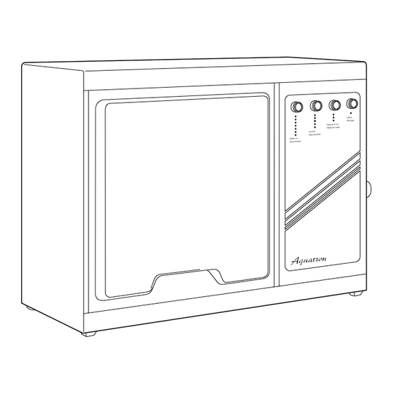
- Page 4 Fig 1: Major component parts A4000 List of Major Components – A4000 Item Description Catalogue Item Description Catalogue number number Perspex Screen – Water Flow Control Switch WS48/1 Cabinet – Reservoir Level Control Boiler Cabinet End Plate – Funnel WF48 Mains Water Inlet with Needle Valve –...
-
Page 5: Assembly
Fig 2 A4000 Assembly Your Aquatron A4000 has been designed Screw thread with ease of assembly specifically in mind, connections Vent pipe but before commencing assembly please study the illustration, fig. 1 on page 2 to Condenser familiarise yourself with the general lay- distillate outlet tube out. - Page 6 THIS EQUIPMENT MUST BE EARTHED! The electrical installation should only be carried out by a qualified electrician. The A4000 is classed as permanently connected equipment. The equipment is supplied with 1.5m of flexible, triple core, circular cable to the following specification:- 1.5mm to BS 6500 or equivalent and <HAR>...
-
Page 7: Operation
4 Press the ON/OFF switch to the ON 11 Safety Cut-Outs The following instructions apply to the A4000 water still where the water feed to position – the switch will illuminate. All Aquatron water stills are protected the boiler is via the mains supply, or a by the following safety devices. - Page 8 Fig 4: Major component parts A8000 List of Major Components – A8000 Item Description Catalogue Item Description Catalogue number number Perspex Screen – Reservoir Level Control Cabinet – Cabinet End Plate – Mains Water Inlet with Needle Valve – Boiler Funnel WF48 Distillate Outlet Pipe (Bench Mounted)
-
Page 9: Assembly
Fig 5 A8000 Assembly Your Aquatron A8000 has been designed with ease of assembly specifically in mind, but before commencing assembly please study the illustration, fig. 4 on page 6 to familiarise yourself with the general lay- out. During assembly, follow the sequence Vent pipe of instructions and do not connect the mains electricity supply until directed. - Page 10 17 Pass the electric cables of the heaters Mains Cable Replacement up into the electrical control If the mains cable requires compartment via the available orifice. replacement, only specially prepared Push the spade terminals onto the spare mains lead obtained from Bibby correct pins of the connecting strip Scientific should be used.
-
Page 11: Operation
A8000 Operation The following instructions apply to the 6 Turn on the mains water supply and Reservoir Control (fig. 11) A8000 Aquatron water still where the using the needle valve item 18, fig. 4, is positioned on the collection water feed to the boiler is via the mains on the side of the cabinet, adjust the reservoir and switches off both the supply, or a header tank. - Page 12 Fig 7: Major component parts A4000D List of Major Components – A4000D Item Description Catalogue Item Description Catalogue number number Perspex Screen – Reservoir Level Control Cabinet – Cabinet End Plate – Boiler (2 off) Mains Water Inlet with Needle Valve –...
-
Page 13: Assembly
A4000D Assembly Fig 8a: Rear To boiler level socket Your Aquatron A4000D has been designed with ease of assembly specifically in mind, but before commencing assembly please study the illustration, fig. 7 on page 10 to familiarise yourself with the general lay- Vent pipe out. - Page 14 16 Refit the metal thermostat probe into 30 Connect the cold water supply to Blue - neutral glass tube of the boiler. Brown - live connection 18 fig. 7. Earth - yellow/green Note: The tubing selected should 17 Take the one metre length of 16mm have a safe working pressure at least tubing and insert through the hole, equal to the pressure of the water...
-
Page 15: Operation
A4000D Operation The following instructions apply to the – The dummy shorting plug is fitted 10 To avoid excessive wastage of coolant A4000D double distillation stills where the to socket item 7, fig. 7. water, make further adjustments to water feed to the first stage boiler is either the needle valve, item 18. - Page 16 Distillate Collection 3 Take the bacteriological filter and connect this to the top of the glass A4000, A8000, feed-pipe using the vinyl tubing provided. Fit the feed pipe and filter A4000D into the reservoir lid via the large screwcap fitting.
- Page 17 CLEAN position the switch illuminates. instructions. to the Level Control WL48 ensuring that the end of the guide tube locates 2 Carefully check the following:– A4000 refer to page 3 in the well at the base. A8000 refer to page 7 –...
- Page 18 1 Litre/Min. for A4000 the scale should be removed on a regular 10 Open Rotaflo stopcock and allow and 2 Litres/Min. for A8000 and basis.
-
Page 19: Fault Finding
Check the condition of the boiler and c) Check that the flow of cooling clean if heavily scaled. water is sufficient. A4000 requires a flowrate of at 7 Distillate collection reservoir least 1 litre/min. floods – A8000, A4000D requires a flowrate Check the location of the Reservoir of at least 2 litres/min. -
Page 20: List Of Spares
Solenoid valve Thermostat for A4000 & A4000D Thermostat for A8000 Thermostat glass tube WTT48 Water Feed Conversion kit WCK/N Float switch for WCK/N WCK/01N Water Flow Control Switch for A4000 WS48/1 Water Flow Control Switch for A8000 & A4000D WS48/2... - Page 21 Circuit diagram for A4000 RESERVOIR FULL ON/OFF CLEAN T1 (S) (AMBER) (WHITE) (WHITE) 3,6,9 1000uF 33uF (E)(S) 2,5,7,8,1 1N4007 12 - WAY SOCKET 1N4007 CLEAN T 125 m AL 1N4007 1N4007 PRESSURE SWITCH 2200uF FLOW (SEE SWITCH NOTE)* 12 - WAY...
- Page 22 NOTE)* 12 - WAY SOCKET 4 - WAY SOCKET A4000/PCB (S) *NOTE SKT1 IS USED IN CONJUNCTION WITH THE DE-IONISED FEED CONVERSION KIT, WCK/N. IF THE STILL IS NOT FITTED WITH WCK/N, PINS 1 & 5 ARE CONNECTED TOGETHER WITH THE 'DIN' PLUG SUPPLIED WITH THE STILL.
- Page 23 12 WAY SKT1/2 SOCKET 4 - WAY SOCKET A4000/PCB (S) *NOTE SKT1 IS USED IN CONJUNCTION WITH THE DE-IONISED FEED CONVERSION KIT, WCK/N. IF THE STILL IS NOT FITTED WITH WCK/N, PINS 1 & 5 ARE CONNECTED TOGETHER WITH THE 'DIN' PLUG SUPPLIED WITH THE STILL.
- Page 24 Thank you for reading this data sheet. For pricing or for further information, please contact us at our UK Office, using the details below. UK Office Keison Products, P.O. Box 2124, Chelmsford, Essex, CM1 3UP, England. Tel: +44 (0)330 088 0560 Fax: +44 (0)1245 808399 Email: sales@keison.co.uk...
Need help?
Do you have a question about the A4000 and is the answer not in the manual?
Questions and answers