
Summary of Contents for QALCOMET HEAT 1
- Page 1 AXIS INDUSTRIES HEAT METER CALCULATOR QALCOMET HEAT 1 TECHNICAL DESCRIPTION USER MANUAL PEQMH1V03 Kulautuvos g. 45a, LT47190 Kaunas, Lithuania tel. (+370 37) 360234; fax. (+370 37) 360358. info@axis.lt www.axis.lt...
- Page 2 This symbol on the product indicates that it will not be treated as household waste. It must be handed over to the applicable take-back scheme for the recycling of electrical and electronic equipment. For more detailed information about the recycling of this product, please contact your local municipal office. Heat meter calculator QALCOMET HEAT 1 PEQMH1V01...
-
Page 3: Safety Information
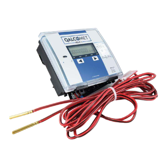
Switch off mains power supply before changing, repairing, connecting or disconnecting system parts! Power switch has to be installed close to the calculator. The heat meter calculator QALCOMET HEAT 1 is made and inspected in compliance with EN61010-1. There are no life dangerous factors, when calculation unit is powered from 3,6 V lithium battery. - Page 4 1. APPLICATION FIELD QALCOMET HEAT 1 is designed for metering and monitoring of heating and cooling energy in closed or open heating/cooling systems, installed in dwelling houses, office buildings or energy plants. The calculator QALCOMET HEAT 1 is a sub-assembly of a heat meter, together with standard flow sensors (based on ultrasonic, electromagnetic or mechanical measurement principle with standard pulse output), temperature and pressure sensors.
- Page 5 Measured volume can be converted into weight expression, using practically measured flow temperature. Heat meter calculator QALCOMET HEAT 1 PEQMH1V01...
- Page 6 Heat meter calculator QALCOMET HEAT 1 PEQMH1V01...
- Page 7 Type reference example for order placing: Calculator QALCOMET HEAT 1 QH1 – □□ – □ – □ – □□ – □□ – □□ – □□ – □□– □ – □ – □– □□*– □□* Type Country code: K1 –Lithuania, K4 - English...
- Page 8 Ultrasonic flow sensor SDU-3 qp15 qp/qi=100 DN50 No flow sensor When placing orders, please find type reference examples for sub- assemblies (flow, temperature and pressure sensors – selected from Chapter 3) in related technical documents. Heat meter calculator QALCOMET HEAT 1 PEQMH1V01...
- Page 9 When the tariff with the condition „T1<T2“ is active, energy Et is calculated by formulas in 1 Table, marked with „*“. Alternate of thermal energy is calculated each 10 s depending on water volume and measured temperatures by formulas, depending on selected measurement scheme (Table 1). Heat meter calculator QALCOMET HEAT 1 PEQMH1V01...
- Page 10 Battery supply and passive pulses Up to 10 200 (5)* 2,5 (100) * (transistor key or mechanical contact) Up to 100 10 (5)* 50 (100) * - values in brackets for pulse input devices class IB Heat meter calculator QALCOMET HEAT 1 PEQMH1V01...
- Page 11 (flow pulse output value), m power, MW 5 0,001 0,1 kWh, 0,0001 Gcal, GJ 50 0,01 0,001 MWh, Gcal, GJ 500 0,01 MWh, Gcal, GJ > 500 0,1 MWh, Gcal, GJ 3000 Heat meter calculator QALCOMET HEAT 1 PEQMH1V01...
- Page 12 3-rd channel fluid temperature 0-160 4 - 40,00 ...+160,00 4-th channel fluid temperature 3-4 3-rd and 4-th channel temperature difference 3- 160 (0...160,00) 5 5-th channel fluid temperature 0-160 - 40,00 ...+160,00 Heat meter calculator QALCOMET HEAT 1 PEQMH1V01...
- Page 13 1000 Hz ( ) – will correspond to the maximum value of the selected range of a current the chosen parameter: flow rate - 160 °C, temperature Heat meter calculator QALCOMET HEAT 1 PEQMH1V01...
- Page 14 Battery 3,6 VDC, D-cell lithium Replacement interval: only for calculator not less than 12 years, for calculator and 2 extra ultrasonic flow sensors not less than 6 years, Heat meter calculator QALCOMET HEAT 1 PEQMH1V01...
- Page 15 Table 5 Amount, Item 1. Heat meter calculator QALCOMET HEAT 1 2. Technical description, user manual for QALCOMET HEAT 1 3. Mounting kit of calculator 3. Internal battery 3,6 V 4. Internal 230 V mains power supply module SKM37 5. Communication module SKS43 with Mbus interface 6.
- Page 16 4. OPERATING PRINCIPLE The calculator QALCOMET HEAT 1 is a sub-assembly of a heat meter, together with standard flow sensors, temperature and pressure sensors. Flow sensors, based on ultrasonic, electromagnetic or mechanical measurement principle, can be used for flow rate measurement. Suitable types of flow sensors are listed in Table 5. Other types of flow sensors can also be used if they correspond to requirements provided in paragraph 2.
- Page 17 Safety requirements for flow, temperature and pressure sensors are provided in appropriate technical documentation. Warning! Switch off mains power supply before changing, repairing, connecting or disconnecting system parts! Power switch has to be installed close to the calculator. Heat meter calculator QALCOMET HEAT 1 PEQMH1V01...
- Page 18 Calculator may be installed in heated premises, on vertical surface. It may not be exposed to direct sunlight. Calculator can be mounted in five different ways: Wall mounting: without possibility sealing of mounting: with possibility sealing of mounting: Mounting on standard DIN-rail: Panel mounting: Heat meter calculator QALCOMET HEAT 1 PEQMH1V01...
- Page 19 2. Readings on the indicator ( for example: “1.00E-2”) are presented in exponential form. There: X.XX E XX Exponent value Base value For example: indicated value 1,25E-2 = 1,25*10 = 0,00125. Heat meter calculator QALCOMET HEAT 1 PEQMH1V01...
- Page 20 Fig. 7.1. Programming the calculator – setting up operation modes. “1, 5, 6, 7, 10, 11, 12, 16E, 17, 18” parameter values have to be ordered individually for each device, and can not be changed during operation. Parameters “21...25” are not displayed in battery-powered version. Heat meter calculator QALCOMET HEAT 1 PEQMH1V01...
- Page 21 value of temperature (by optical interface– 2) difference 1-2 and report language : L - For example: 2 For example lithuanian LCD segment test Segmentų testas Heat meter calculator QALCOMET HEAT 1 PEQMH1V01...
- Page 22 Sequence of displayed parameters may vary depending on selected measurement scheme and number of sensors installed. Note. The displayed parameters listing order can vary or some parameters aren’t displayed depending on regional user requirements. Heat meter calculator QALCOMET HEAT 1 PEQMH1V01...
- Page 23 (0-5 mA, 0-20 mA or 4-20 mA) set pressure values for provided pressure sensors that correspond to upper designated current limit. Setting and verifying other parameters: - set customer ID number Heat meter calculator QALCOMET HEAT 1 PEQMH1V01...
- Page 24 M-bus, CL or RS-232 interface is activated by plugging in the jumpers “CL – M-bus – RS- 232” in such way, that required interface type appears beside the terminal pins “73…75”. Marking on the jumper board will show the functional description of the pins. Heat meter calculator QALCOMET HEAT 1 PEQMH1V01...
- Page 25 Measured parameter values should be indicated on the display, if the heat meter (calculating unit, flow, pressure and temperature sensors) is installed correctly. If measured parameter values are not displayed correctly, it is necessary to verify the installation. Heat meter calculator QALCOMET HEAT 1 PEQMH1V01...
- Page 26 Daily archive data is being printed (displayed) Monthly archive data is being printed (displayed) Test mode TEST Parameterization mode 4. Measurement units Volume (mass) /h (t/h) Flow rate Pressure Temperature, temperature difference GJ, Gcal, MWh, kWh Energy Power Hours Heat meter calculator QALCOMET HEAT 1 PEQMH1V01...
- Page 27 - previous parameter (Fig. 8.4). Sequence of displayed parameters may vary depending on selected measurement scheme and number of sensors installed. To return to the instantaneous parameters level, press and hold button . Heat meter calculator QALCOMET HEAT 1 PEQMH1V01...
- Page 28 5-th channel fluid volume (or mass) 2-nd channel fluid volume (or mass) Operating time (without energy calculation error), hours Fig. 8.4. Displaying integral parameter values Heat meter calculator QALCOMET HEAT 1 PEQMH1V01...
- Page 29 Status of sensor 4 Status of sensor 5 Error code description: 0 - no error, normal operation, 1 – temperature difference is under programmed minimum allowed value, 8 - sensor failure (open circuit or short circuit). Heat meter calculator QALCOMET HEAT 1 PEQMH1V01...
- Page 30 Temperature difefrence 1- 2 Flow rate on 2-nd 2-nd channel fluid channel q2 pressure p2 Fig. 8.5 Displaying instantaneous parameter values Heat meter calculator QALCOMET HEAT 1 PEQMH1V01...
- Page 31 Zone A Zone B Parameter code Parameter value Shortly pressing button while parameter is displayed will allow to select desired time point or interval. List of parameters is presented in the Table 8: Heat meter calculator QALCOMET HEAT 1 PEQMH1V01...
- Page 32 5 – flow rate below or exceeds programmed max and min values, or temperature difference below programmed minimum value, 8 – flow or temperature sensor error, d - simultaneous occurrence of errors “5” and “8” Heat meter calculator QALCOMET HEAT 1 PEQMH1V01...
- Page 33 Time when flow rate q2 is below programmed minimum allowed value Time when flow rate q3 is below programmed minimum allowed value Time when flow rate q4 is below programmed minimum allowed value Heat meter calculator QALCOMET HEAT 1 PEQMH1V01...
- Page 34 . Define the following report options by shortly pressing button : - report type Ac – printing consolidated report, Er – printing error list, In – printing current values if integral parameters, CF – printing device configuration parameters, Heat meter calculator QALCOMET HEAT 1 PEQMH1V01...
- Page 35 “vR” will be displayed. Pressing button one more time will start opening the valve – symbol “^R” will be displayed. Pressing button once again will switch off valve control – only symbol “R” will be displayed. Heat meter calculator QALCOMET HEAT 1 PEQMH1V01...
- Page 36 - To read out all measured data and the data from calculator archive - To read out and change the settings of regulator - To read out the configuration settings of calculator. In parameterization mode "SET" (this can be activated by pressing the button "SET"): Heat meter calculator QALCOMET HEAT 1 PEQMH1V01...
- Page 37 11.2. Warranty period - 12 months from bringing into operation, but not more than 18 months from manufacturing date. Manufacturer’s address: AB “AXIS INDUSTRIES”, Kulautuvos g. 45a, LT47190 Kaunas, Lithuania tel. (+370 37) 360234; fax. (+370 37) 360358. info@axis.lt www.axis.lt Heat meter calculator QALCOMET HEAT 1 PEQMH1V01...
- Page 38 12. ACCEPTANCE CERTIFICATE 12.1. QALCOMET HEAT 1 , serial Nr....…. corresponds to LST EN 1434 requirements and may be put into operation. Signature ......Date of production : Heat meter calculator QALCOMET HEAT 1 PEQMH1V01...
- Page 39 Heat meter calculator QALCOMET HEAT 1 PEQMH1V01...
- Page 40 Heat meter calculator QALCOMET HEAT 1 PEQMH1V01...
- Page 41 Heat meter calculator QALCOMET HEAT 1 PEQMH1V01...
- Page 42 Heat meter calculator QALCOMET HEAT 1 PEQMH1V01...
- Page 43 3. Flow sensor V2 connection diagram for energy measurement algorithm “3 – winter / summer” is presented in Fig. B5. In this case flow sensor V4 not available. 4. Diagram for connecting the regulating valve is presented in Fig. B4. Heat meter calculator QALCOMET HEAT 1 PEQMH1V01...
- Page 44 3. Flow sensor V2 connection diagram for energy measurement algorithm “3 – winter / summer” is presented in Fig. B5. In this case flow sensor V4 not available. 4. Diagram for connecting the regulating valve is presented in Fig. B4. Heat meter calculator QALCOMET HEAT 1 PEQMH1V01...
- Page 45 4-wire conection method of temperature sensors and jumper “+U” is in position “+18V” b) when pressure sensors are connected using three-wire connection and power is supplied from the calculator (+18V) Fig. B3. Other options to connect pressure sensors. Heat meter calculator QALCOMET HEAT 1 PEQMH1V01...
- Page 46 Remark: Flow sensor V2 should generate addition flow direction indication signal (electrical parameters should be identical as pulse output parameters): log.1 (or open input) – when fluid flows in forward direction; log.0 (or shorted input) – when fluid flows in reverse direction. Heat meter calculator QALCOMET HEAT 1 PEQMH1V01...
- Page 47 74 (Tx) 75 (GND) - DTR +RTS Fig.B6. Scheme of direct connection of calculator to interface RS-232 of PC Fig.B7. Scheme of direct connection of calculator to interface RS-232 of modem or printer Heat meter calculator QALCOMET HEAT 1 PEQMH1V01...
- Page 48 25, (74) Ground for RS-232 interface “GND” ˇ Relay output “decrease” Relay output ground ˆ Relay output “increase” ╧ Main ground 230V Mains power supply (230V AC) 230V Mains power supply (230V AC) Heat meter calculator QALCOMET HEAT 1 PEQMH1V01...
- Page 49 D1.1. Adapter plate according to figure 8 of EN1434-2:2007 for wall mounting of calculator It can be used for wall mounting, if the aperture in the wall is too large for the calculator 1 – calculator QALCOMET HEAT 1 2 – adapter plate 3 –...
- Page 50 Annex D cont. D2. Wall mounting, without possibility sealing of mounting D3. Wall mounting, with possibility sealing of mounting D4. Mounting on standard DIN-rail Heat meter calculator QALCOMET HEAT 1 PEQMH1V01...
- Page 51 Annex D cont. D5. Panel mounting a) DN (25,32) b) DN 50 D6. Mounting on flow sensor type SDU-1. Flow temperature max. 90 Heat meter calculator QALCOMET HEAT 1 PEQMH1V01...
- Page 52 Heat meter calculator QALCOMET HEAT 1 PEQMH1V01...
Need help?
Do you have a question about the HEAT 1 and is the answer not in the manual?
Questions and answers