Table of Contents
Advertisement
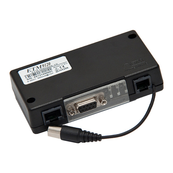
ETM9120 9140 Configuration Tool Userguide201406RV001
UMTS/GSM/GPRS Terminal – ETM9140-1
GSM/GPRS Terminal – ETM9120-1
Configuration Tool Userguide
Features:
◩ 3G (HSPA+/UMTS) Connectivity – ETM9140-1 only
◩ 2G (GSM/GPRS) Connectivity
◩ Standard RS232 9DF serial port
◩ 5v to 35v power input on RJ12 connector
◩ 7 x I/O's on RJ45 connector
◩ FME M antenna connector
◩ Sleep Mode for reduced power consumption
◩ User configurable via configuration tool
Advertisement
Table of Contents

Summary of Contents for ETM ETM9120-1
- Page 1 ETM9120 9140 Configuration Tool Userguide201406RV001 UMTS/GSM/GPRS Terminal – ETM9140-1 GSM/GPRS Terminal – ETM9120-1 Configuration Tool Userguide Features: ◩ 3G (HSPA+/UMTS) Connectivity – ETM9140-1 only ◩ 2G (GSM/GPRS) Connectivity ◩ Standard RS232 9DF serial port ◩ 5v to 35v power input on RJ12 connector ◩...
- Page 2 Page 2 of 46 For Support Contact +61-2-9956-7377 Or support@etmpacific.com.au Contents Contents ............................2 Document ............................4 History ............................4 Relevant Documents ........................4 Abbreviation ..........................4 Introduction ............................5 Overview............................5 Nomenclature ..........................5 Using the Configuration tool ......................5 Installation .............................
- Page 3 Page 3 of 46 For Support Contact +61-2-9956-7377 Or support@etmpacific.com.au Connect to ISP or Server ......................20 Data Transfer Tab ........................... 21 Setting the SWT Timers ......................21 Functional Timing Description ..................... 22 Heart Beat package ........................23 Ping Sending ..........................23 Analogue Values .........................
-
Page 4: Document
The documents listed below are useful for the understanding of this document. Document ID/No. Title 2005-0001 57 ETM Modems ET Communication Spec 2003-0003 16 ETM Modems TCP UDP Port Configuration Spec 2005-0001 17 ETM Modems TCP UDP Protocol Spec ETM9140 9120 Quick Start ETM9120 9140 Quick Start Guide Guide 201405RV01... -
Page 5: Introduction
Or support@etmpacific.com.au Introduction This document describes the operation of two ETM modems and therefore within this document both types of product are referred to with the generic term of ‘wireless modem’ and wherever there is a distinction required between the two there a clearly identified header will be shown for each type of product;... -
Page 6: Initial Start-Up And Programming
– if you do not then contact ETM and request the appropriate version or visit the support section of ETM’s website. -
Page 7: Saving, Reading And Writing Configuration Files
Page 7 of 46 For Support Contact +61-2-9956-7377 Or support@etmpacific.com.au You are now ready to use the configuration tool to make changes to the wireless modem. Once you are familiar with the Configuration Tool you can shorten the procedure, if the ... -
Page 8: Alarm / Message Tab
Page 8 of 46 For Support Contact +61-2-9956-7377 Or support@etmpacific.com.au Alarm / Message Tab The unit can send messages based on inputs to up to 5 mobile users. SMS phone numbers and user ID SMS Central is taken from the SIM-card and cannot be changed. Number 1 –... -
Page 9: Use Incoming Security Filter
Page 9 of 46 For Support Contact +61-2-9956-7377 Or support@etmpacific.com.au If you want to enter a textual ID then enter it into the text box and uncheck the two checkboxes above You have forty (40) characters available and we suggest that you use the shortest practical ID possible as there are only 160 characters available in an SMS and if you use 40 characters for the ID this leaves only 120 characters for the content of the SMS which may limit the information that can be sent. -
Page 10: I/O Settings
Digital Output: LL0V, HL3V,0.1mA ◩ Analogue Input: 0-2.5VDC, Max Input 50VDC IO7 can also be used as a „toggled“ output in combination with the ETM IO board to provide switched sensor power supply – contact ETM for more details IO 1 & 2... -
Page 11: Alarm Restore Delay
Allows for high level, low level or both with hysteresis. Do not use the “Use self adjusted Alarm level with deviation from reference, when alarm is activated” option without consulting ETM. Hysteresis can be set, this is useful in eliminating nuisance alarms resulting from analogue ... -
Page 12: A/D Cal Param
Page 12 of 46 For Support Contact +61-2-9956-7377 Or support@etmpacific.com.au A/D Cal Param Shows the current calibration/scaling parameters for the input, refer section on calibration for more information IO7 can be used to toggle when logging occurs as a signal to switch power supply to a sensor, ... -
Page 13: Udp Server Selection
Page 13 of 46 For Support Contact +61-2-9956-7377 Or support@etmpacific.com.au UDP Server Selection Allows for the sending of alarms via UDP ETM9120 9140 Configuration Tool Userguide201406RV001... -
Page 14: Settings Tab
Page 14 of 46 For Support Contact +61-2-9956-7377 Or support@etmpacific.com.au Settings Tab UMTS/GPRS Module <--> MCU and MCU <--> Port UMTS/GPRS Module <--> MCU should match MCU <--> Port. MCU <--> Port sets the serial port on the wireless modem and should be adjusted to suit your device connected to the port. -
Page 15: Setting The Internal Modules Baud Rate
Page 15 of 46 For Support Contact +61-2-9956-7377 Or support@etmpacific.com.au Setting the Internal Modules Baud Rate Change to AT Mode using the ETSC1 command, this can be sent using the drop down box on the bottom left or by typing into the terminal window Common ET commands can be found and sent from... - Page 16 Page 16 of 46 For Support Contact +61-2-9956-7377 Or support@etmpacific.com.au Send --- to return to command mode and continue programming the unit. If the baud rate set in the settings tab does not match the modules baud rate then an error similar to that shown below on start-up will occur, when the unit is started in run mode.
-
Page 17: Normal/Typical Start Sequence
Page 17 of 46 For Support Contact +61-2-9956-7377 Or support@etmpacific.com.au To solve the above problem wait until the ETM9910 SYSTEM START message appears and press the ESC key to put the unit into escape mode for programming, if successful the screen should look as follows. -
Page 18: Internet Tab
Page 18 of 46 For Support Contact +61-2-9956-7377 Or support@etmpacific.com.au Internet Tab This section has settings which controls how the unit communicates over the internet with a server. Remote server IP Address 1 and 2 are a pair of addresses that can be used on the Internet Transfer page. ... -
Page 19: Isp Dial Up Login
Page 19 of 46 For Support Contact +61-2-9956-7377 Or support@etmpacific.com.au If you are sure that there is always a defined character on the end of a line to be sent enter the HEX representation of the ASCII value for that character and select ‘Use Termination’. You should always start entering the termination character (string) from the left hand side of the entry area and any entries that are not used should have FF entered. -
Page 20: Connect To Isp Or Server
Page 20 of 46 For Support Contact +61-2-9956-7377 Or support@etmpacific.com.au Password Is the appropriate password for the service being utilised. Connect to ISP or Server Connect to ISP at start-up When the unit powers up it can automatically connect to the ISP. Connect to Server at start-up ... -
Page 21: Data Transfer Tab
SWT3 – This timer sends the current values as configured. The sending port will be 2800. SWT4 – This timer sends the current values as configured. The sending port will be 2880. The data types are defined in the separate document, ‘ETM Modems TCP UDP Protocol spec’. Setting the SWT Timers Setting the SWT timers is done by clicking on the Terminal tab and then clicking on the terminal window, so that a flashing cursor is displayed. -
Page 22: Functional Timing Description
Page 22 of 46 For Support Contact +61-2-9956-7377 Or support@etmpacific.com.au Functional Timing Description The presented configuration delivers the following solution (the intervals may not be representative of a valid setup but they are acceptable for this description): STW2 - Causes the archived/logged data in any selected inputs to be sent every 10 minutes, ... -
Page 23: Heart Beat Package
Page 23 of 46 For Support Contact +61-2-9956-7377 Or support@etmpacific.com.au Heart Beat package Note: This feature has the potential to cause you issues if your carrier does not support short interval sending with minimal data content. Check your carriers terms of usage before you start to use these features. -
Page 24: Analogue Values
Page 24 of 46 For Support Contact +61-2-9956-7377 Or support@etmpacific.com.au Analogue Values Default (presented in mV) Analogue values, sent by TCP, UDP or SMS are presented in mV, the range of each analogue input is 0-2500mV Scaled with calibrated values ... -
Page 25: Terminal
Page 25 of 46 For Support Contact +61-2-9956-7377 Or support@etmpacific.com.au Terminal In the terminal window you can see the output from the unit and type commands to the unit. Note : Remember to place the cursor inside the window before you type any commands. Entering command mode Place the cursor inside the window and press “escape”... -
Page 26: Main Init
3G/WCDMA– contact ETM should you wish to use this feature Force Send Data when in Module Direct Used for background sending of data collected by the unit when in AT mode – contact ETM should you wish to use this feature Force SW reset every 24 hours ... -
Page 27: Init At-Command Table
Page 27 of 46 For Support Contact +61-2-9956-7377 Or support@etmpacific.com.au If the modem remains inactive for more than x minutes the unit will reset Configuration ID No An ID that can be used to further identify a unit configuration, may be used to identify standard configurations for a particular application. - Page 28 Page 28 of 46 For Support Contact +61-2-9956-7377 Or support@etmpacific.com.au Periodic Timer Setting Refer to the description of Periodic versus Synchronizes to Real Time Clock in the ‘Internet Data Transfer’ section for a description of the differences between these two timing methods Min Awake Time ...
-
Page 29: Active Profile
Page 29 of 46 For Support Contact +61-2-9956-7377 Or support@etmpacific.com.au Reducing the scanning interval can provide power savings as the action of scanning an Analogue input requires a small power burden when the Analogue inputs are powered up to take a reading, in addition if IO7 is being used to switch sensor power then reducing the frequency at which the sensor is turned on will save power. - Page 30 Page 30 of 46 For Support Contact +61-2-9956-7377 Or support@etmpacific.com.au Signal Quality:-85dBm(14)"Low" Signal Quality:-85dBm(14)"Low" SMS Message Service OK SIM:SMS Central no:+61418706700 SUPPL VOLT:15.62V The wireless modem would be ready to use once the ‘SUPPL VOLT:’ message was received For standard ET mode operation (as say an SMS alarm) you would have all options checked. ETM9120 9140 Configuration Tool Userguide201406RV001...
-
Page 31: Logging Tab
Page 31 of 46 For Support Contact +61-2-9956-7377 Or support@etmpacific.com.au Logging Tab A limited amount of data can be stored in memory during periods of network outages or if sleep mode is used. Data Logging On (Timed) On (Timed/Event on IO1) ... -
Page 32: Logging Slots Available
Page 32 of 46 For Support Contact +61-2-9956-7377 Or support@etmpacific.com.au The logging interval timer SWT1 needs to be set in the terminal window using the ETSW=1,YY:YY,X command where; YY:YY is the nominated start time and X is the interval in whole minutes. -
Page 33: Hardware Description
◩ Analogue Input: 0-2.5VDC, Max Input 50VDC IO7 can also be used as a „toggled“ output in combination with the ETM IO board to provide switched sensor power supply – contact ETM for more details ETM9120 9140 Configuration Tool Userguide201406RV001... -
Page 34: I/O Connector Pins
Page 34 of 46 For Support Contact +61-2-9956-7377 Or support@etmpacific.com.au I/O Connector pins Each I/O Connector pin is protected by a RC coupling that is displayed in the figure below. Connector To Micro Controller R1 = 1 M, R2= 33 K C1 = 4,7nF C2 = 0,1uF All pins have the same protecting circuit, whether they are used for digital or analogue signals, or... -
Page 35: Sim Card
Page 35 of 46 For Support Contact +61-2-9956-7377 Or support@etmpacific.com.au SIM Card The SIM card connector is located on the underside of the ETM9xxx-xxx Terminal. The unit supports both 3V or 1.8V SIMs. Any SIM card used needs to be correctly provisioned for the services and network upon which it is intended to be used. -
Page 36: Indicator Lights
Page 36 of 46 For Support Contact +61-2-9956-7377 Or support@etmpacific.com.au Indicator Lights ETM9xxx-xxx Status LEDs Blue YELLOW Green UMTS MCU Status Signal Strength Indication During Start-up Signal < 10 10 ≤ Signal < 15 15 ≤ Signal < 20 20 ≤ Signal < 25 25 ≤... -
Page 37: Low Power Mode (Lpm) Example/Description
Low Power Mode (LPM) Example/Description [Setup Information] 15:24:21.32 : ETM9140 SYSTEM START 15:24:27.49 : SUPPL VOLT:14.72V 15:24:28.57 : ETM Matteknik AB 71224 9140 SW2.0.1.15 20140218 CT0600 Escape Pressed > 15:24:31.19 : ETSWT? 1,PTL:1,1 2,PTL:2,2 3,PTL:2,2 4,PTL:5,5 5,PTL:10,10 15:24:38.78 : et&sr SW RESET:Cmd... - Page 38 Page 38 of 46 For Support Contact +61-2-9956-7377 Or support@etmpacific.com.au expired then a final send may be undertaken and then the wireless modem would move immediately to LPM:OFF – when you see this in the log you could assume that the wireless modem had performed the required tasks incorrectly when it had in fact done the best that it could do based on the configuration.
-
Page 39: Real Time Clock And Reference Date
Page 39 of 46 For Support Contact +61-2-9956-7377 Or support@etmpacific.com.au Real time Clock and reference date Reference Date Description The wireless modem uses the reference date as a base to time and date any subsequent alarms or data that is processed. Real Time Clock Description The wireless modem will use the real time clock as an incrementing value to add to the reference date for any alarms or data that is processed. -
Page 40: I/O 7 Toggling
6: You cannot drive a sensor or a relay directly from the output so you can either purchase an optional IO Board from ETM or you could build a circuit similar to the following (we do not offer support for circuit design so you should ascertain for yourself whether a circuit is appropriate for your use or not). - Page 41 Page 41 of 46 For Support Contact +61-2-9956-7377 Or support@etmpacific.com.au ETM9120 9140 Configuration Tool Userguide201406RV001...
-
Page 42: Calibration Of Analogue Inputs
Page 42 of 46 For Support Contact +61-2-9956-7377 Or support@etmpacific.com.au Calibration of Analogue Inputs Analogue inputs can only be scaled/calibrated by connecting a known source input to the particular IO and following the procedure outlined below. This procedure uses the ET command ETSAC=X,YY,ZZ,AA,BB Where: X=I/O number 3 thru 5 YY = First scaling point... - Page 43 Page 43 of 46 For Support Contact +61-2-9956-7377 Or support@etmpacific.com.au Ensure you write the changes to the unit. 2. Connect Multifunction calibrator or voltage source to IP-NO and Common of I/O3 on the IO board 3. Power up the IO board and the modem, press/send “ESC” key to put the unit into ESC mode (see Using the Configuration Tool for further details on using ESC mode) 4.
- Page 44 Page 44 of 46 For Support Contact +61-2-9956-7377 Or support@etmpacific.com.au First Point Set, Set Next. Send SPACE when done! 8. Set the Multifunction calibrator to 2V output, then press “SPACE” key to finish You need to finish steps 6 through 8 within the 20 seconds timeout period. You can increase the timeout value from 20 to 30.
-
Page 45: Querying/Programming The Modem Using Et Commands
ETRAI3 for analogue status of IO3. These commands could have been sent by SMS or by IP. For more details on the available ET commands refer “ETM Modems ET Communication Spec. ETM9120 9140 Configuration Tool Userguide201406RV001... - Page 46 Tel: +46 (0)8 25 28 75 Tel: +61 (0)2 9956 7377 Fax: +46 (0)8 80 11 10 Fax: +61 (0)2 9956 5791 Email: etm@etm.se Email: info@etmpacific.com.au Web: www.etm.se Web: www.etmpacific.com.au © ETM Pacific Pty Ltd · Subject to change without notice.
Need help?
Do you have a question about the ETM9120-1 and is the answer not in the manual?
Questions and answers