Table of Contents
Advertisement
Quick Links
Advertisement
Table of Contents

Summary of Contents for AMK OWR 20
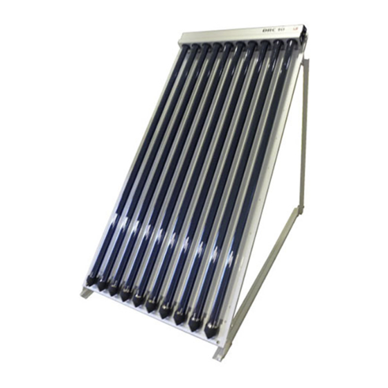
- Page 1 05/14 OWR 20 360° Vacuum Tube Collector Planning/Installation/ Commissioning OWR 20 optimized without reflector Should you have any technical questions, please contact your sales Manufactured in Switzerland by consultant of your supplier. www.amk-collectra.ch Distributed by www.amk-solac.com...
-
Page 3: Table Of Contents
Ia Tiled roofs Ib Flat roofs II Commissioning IIa System and dimensioning - South and east/west systems - OWR 20 dimensioning IIb Hydraulic connections IIc Expansion vessel - Expansion vessel calculation - Intrinsically safe solar system - Example: expansion vessel calculation... -
Page 4: Data
Frost risk transported carefully and may not Outdoor pipes with no flow- with the collector pipe either be dropped or thrown. AMK-Col- vertical or horizontal. However, through are bound to be at risk lectra AG cannot extend warranty the application is optimised from frost. -
Page 5: General Planning Notes
Depending on the installation angle the „Concrete bases long“ (BS-L) may need to be loaded with additional BS-A elements. For 1 pc. angular frame OWR 20 the following number of attachments (BS-A) per BS-L is required: (These numbers are valid for collector fields with 2 collectors and more (3 angular frames and more)). -
Page 6: I Installation
I Installation Ia Roof-mounted installation on tiled roofs Example: installation of 2 OWR 20 collectors - 13mm socket spanner/open-ended spanner - 30mm open-ended spanners (2 x) - Ø 5.5mm wood drill bit - hammer - hacksaw - folding ruler/metre rule... - Page 7 Remove tiles which cover the rafters where the mounting an- gles are to be installed. It may be necessary to adjust the mounting angles to the tile height, and to insert a wooden support beneath them. Use the hacksaw and hammer to remove a section of tile, so that the mounting angle can lie in a tile recess.
- Page 8 Protruding tile edges must be knocked off before replacing the tiles. Before mounting the connec- tors, one T-head bolt is to be inserted into each mounting an- gle. connector which screwed together at the begin- ning is to be screwed in place, in line with the rows of tiles.
- Page 9 Lie the OWR 20 in a horizontal position at a practical working height. The collector hook set will be needed during installation. The two collector hooks at the head of the collector are to be precisely measured with the metre rule.
- Page 10 Some pressure must be applied to insert the other expansion joints. All expansion joints must be tightened at both ends diametri- cally opposed in order to pre- vent excessive tightening on one side! (torque max. 15 Nm) Slight tilting makes it easier to attach the expansion joints, whereupon the seal must not become damaged.
- Page 11 I Installation Ib Installation on flat roofs Example: installation of 2 OWR 20 collectors - 13mm socket spanner/open-ended spanner - 30mm open-ended spanners (2 x) - Ø 5.5mm wood drill bit - hammer - hacksaw - folding ruler/metre rule The installation materials in-...
- Page 12 Slide the slot nut for the base section and for the extension section into the collector frame. The slot nut and the collector frame join flush with one an- other. The pivot bolt is not yet to be fastened. Tighten the other bolts.
- Page 13 The final step is to fasten the pivot bolts at the lower end of the supports. The standing sup- ports are pre-configured in the factory for approximately 40°. The collector can be mounted at a more shallow angle by moving the lower end inwards.
- Page 14 A Internal return pipe / B Collector inlet / collector inlet cold The two OWR 20 collectors have now been mounted on their mounting frames and hydrauli- cally interconnected. In the next step, the entire col- lector array is to be fastened to the base surface by means of the clamping plates.
-
Page 15: Ii Commissioning
II Commissioning IIa System and dimensioning South-facing roof Collector array with two OWR 20 collectors, a pump group and control unit. The roof fac- es south, south-east, or south- west. Legend Collector sensor Storage tank sensor Pump group (solar station) Expansion vessel TMV 3-way thermomixer Roof facing EAST/WEST... - Page 17 OWR 20: 1,7 l/min Large-scale systems (Tichelmann) U-pipe from A to B Large-scale systems, e.g. more than 6 OWR 20 collectors in a row, can be connected together in the centre of the array for quick, low-loss yields. Volume flow: max.
-
Page 18: Iic Expansion Vessel
II Commissioning IIc Expansion vessel Intrinsically safe system, see also next page Expansion vessel calculation Calculation Vessel selection according to For correct dimensioning of an SKWI 93-1 expansion vessel, the following It must be possible for the ex- system data must be known: pansion vessel to take in at least - Total system content V S , (i.e. -
Page 19: Intrinsically Safe Solar System
Connecting the expansion vessel The expansion vessel con only ing off must be installed before temperature. The connection is be connected to the AMK col- the expansion vessel. to be made at the outlet side lectra ag pumps group, if it is a... - Page 21 - Water volume of solar circuit approx. 2.5 litres - Water volume of heat exchanger approx. 3.0 litres Calculation of solar system's water content: - Collectors 3 x OWR 20; 3 x 3.5 litres 10.5 litres - Solar circuit 2.5 litres - Heat exchanger 3.0 litres...
- Page 22 Example (continued): Calculation/installation of expansion vessel II N.B.: The pre charge pressure (air side) at the expansion vessel is set directly at the expansion vessel by means of a manometer. The valve is situated in the middle of the expansion vessel. Normally, the tank pressure is set high enough in the factory so that it only has to be reduced to the pre charge pressure level.
-
Page 23: Iid Protective Devices
II Commissioning IId Protective devices Lightning protection As a general rule, all electrical circuit piping is to be connected devices must be earthed with to the building's equipotential a metal housing. This also ap- bonding via a short route. plies to solar systems. Pump group, pipes, storage tank and Connect the connector to the collectors must be equipped... -
Page 24: Iie Maintenance/Repair
II Commissioning IIe Maintenance/Repair Tube replacement/Collector removal Tube replacement Tube replacement (with collector removal) (without collector removal) If there is insufficient space to pull out the tubes at the lower end, the collector must be removed. Squeeze together the cover's Note: Bring the system to a standstill, release pressure and water.
Need help?
Do you have a question about the OWR 20 and is the answer not in the manual?
Questions and answers