Table of Contents
Advertisement
Advertisement
Table of Contents

Related Manuals for Asus E520


Summary of Contents for Asus E520
- Page 1 Mini Desktop PC E520 User Manual...
- Page 2 ASUS will only be responsible for or indemnify you for loss, damages or claims based in contract, tort or infringement under this Warranty Statement. This limit also applies to ASUS’ suppliers and its reseller. It is the maximum for which ASUS, its suppliers, and your reseller are collectively responsible.
-
Page 3: Table Of Contents
Quickly enter the BIOS ..................29 Load default BIOS settings ................29 Upgrading your PC Installing 2.5” hard disk drive / solid state drive ........32 Upgrading memory modules ..............37 Installing or upgrading the wireless card ..........38 Installing or upgrading the M.2 SSD ............39 E520... - Page 4 Appendix Safety information ...................42 Setting up your system.................42 Care during use ....................43 Regulatory notices ...................44 ASUS contact information ................48 E520...
-
Page 5: About This Manual
VivoMini's data and components. Typography Bold text Indicates a menu or an item to select. Italic This indicates sections that you can refer to in this manual. E520... -
Page 6: Package Contents
• * Actual product specifications and package contents may vary depending on the model type, country, or region. • I f the device or any of its components fail or malfunction during normal or proper use and it is still within the warranty period, bring the device and the warranty card to you nearest ASUS Service Center. E520... -
Page 7: Getting To Know Your Pc
Getting to know your PC... -
Page 8: Features
PC to external devices. Docking (optional) The docking is an optional accessory to your PC. It contains an optical disc drive and additional I/O ports for external device connectivity. NOTE: The Docking may vary depending on the model type, country, or region. E520... -
Page 9: Main Box
PC to sleep mode. Air vents The air vents allow air to enter and leave your PC chassis. IMPORTANT! For optimum air flow, ensure that the air vents are free from obstructions. E520... - Page 10 The eight-pin RJ-45 LAN port supports a standard Ethernet cable for connection to a local network. HDMI port The HDMI (High Definition Multimedia Interface) port supports a Full-HD device such as an LCD TV or monitor to allow viewing on a larger external display. E520...
- Page 11 WARNING! The power adapter may become warm to hot when in use. Do not cover the adapter and keep it away from your body. Kensington® security slot The Kensington® security slot allows you to secure your PC using Kensington® compatible security products. E520...
- Page 12 The jack is used to connect the supplied wireless antenna to enhance wireless signal reception. Air vents The air vents allow air to enter and leave your PC chassis. IMPORTANT! For optimum air flow, ensure that the air vents are free from obstructions. E520...
- Page 13 It also provides additional support to ensure that your device is held securely in place. Screw hole for the PC stand This screw hole allows you to attach and secure your PC with its bundled stand. E520...
- Page 14 PC while laid on a flat surface with the bottom side down and also covers the chassis screws of your PC. Screw holes for the optional docking This screw hole allows you to connect and secure your PC with its optional docking. E520...
-
Page 15: Docking (Optional)
Optical Disc Drive manual eject hole The manual eject hole is used to eject the drive tray in case the electronic eject button does not work. WARNING! Use the manual eject hole only when the electronic eject button does not work. E520... - Page 16 The 9-pin serial (COM) connector allows you to connect devices that have serial ports such as mouse, modem, or printers. Parallel port This parallel port allows you to connect your PC to external devices that use parallel port connectors, such as printers and scanners. E520...
- Page 17 PC. NOTE: For more details, refer to the Connecting the optional docking to the main box section in this user guide. Main box latches These latches allow you to securely attach the main box to the docking. E520...
- Page 18 PC while laid on a flat surface with the bottom side down and also covers the chassis screws of your docking. Screw holes for the VESA mount These screw holes allows you to connect and secure your PC to a VESA mount. E520...
-
Page 19: Using Your Pc
Using your PC... -
Page 20: Connecting The Optional Docking To The Main Box
If you purchased the optional docking together with the main box, refer to the following steps to setup the docking with your PC. Attach two bundled screws on the bottom side of the main box. Detach the USB bridge from the USB bridge compartment. USB bridge E520... - Page 21 Gently push the main box to the left to completely attach it with the docking. Attach the USB bridge into its designated USB 2.0 ports on the main box and the docking. E520...
-
Page 22: Getting Started
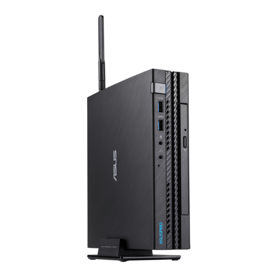
NOTE: The illustrations in this section are for reference only and may vary per model. Connecting the wireless antenna Connect the wireless antenna to your PC to enhance the wireless signal. Ensure that the wireless antenna is in an upright position (90° angle) to get the best wireless reception. E520... -
Page 23: Mounting Your Pc On The Stand
Align the stand’s mounting hole with the mounting hole on your PC, then secure it in place with the stand screw. stand screw IMPORTANT! Ensure that your PC is mounted on its stand before placing it on a stable and flat surface. E520... -
Page 24: Connect The Usb Cable From Keyboard Or Mouse
PC. You can also connect a USB dongle for a wireless keyboard and mouse set. To connect a keyboard and mouse to your VivoMini: Connect the USB cable from your keyboard and mouse to any of the USB ports of your PC. NOTE: The keyboard varies with country or region. E520... -
Page 25: Connect A Display Panel To Your Pc
• HDMI connector • DisplayPort connector To connect a display panel to your PC: Connect one end of an HDMI, or a DisplayPort to an external display, and the other end of the cable to your PC’s HDMI, or DisplayPort. E520... -
Page 26: Connect The Ac Power Adapter To Your Pc
Connect the DC power connector into your PC’s power (DC) input. Plug the AC power adapter into a 100V~240V power source. IMPORTANT! • W e strongly recommend that you use only the AC power cord that came with your PC. • W e strongly recommend that you use a grounded wall socket while using your PC. • T he socket outlet must be easily accessible and near your PC. • T o disconnect your PC from its main power supply, unplug your PC from the power socket. E520... -
Page 27: Turn On Your Pc
Turn on your PC Press the power button to turn on your PC. E520... -
Page 28: Turning Your Pc Off
BIOS Setup. • You have installed a new system component that requires further BIOS settings or update. WARNING! Inappropriate BIOS settings may result to instability or boot failure. We strongly recommend that you change the BIOS settings only with the help of a trained service personnel. E520... -
Page 29: Quickly Enter The Bios
To load the default values for each of the parameters in your BIOS: • Enter the BIOS by following the steps mentioned in the Quickly enter the BIOS section. • Navigate to the Exit menu. • Select the Load Optimized Defaults option, or you may press <F5>. • Select Yes to load the default BIOS values. E520... - Page 30 E520...
-
Page 31: Upgrading Your Pc
Upgrading your PC... -
Page 32: Installing 2.5" Hard Disk Drive / Solid State Drive
To install or upgrade the hard disk drives / solid state drives: Turn off your PC then disconnect all cables and peripherals. Remove the antenna from your PC, then remove the optional docking. Place the PC on a flat stable surface, with the side with the rubber feet facing upwards. E520... - Page 33 (4) screws securing the bottom cover. Push the bottom cover from the left side towards the right side. Lift the bottom cover from the left side to remove the bottom cover. E520...
- Page 34 HDD/SSD before installing a new HDD/SSD. This may vary depending on the model type, country or region. Remove the three (3) screws from the bracket (A), then remove the bracket (B). Secure the HDD/SSD to the bracket using four (4) screws. E520...
- Page 35 12. Carefully place the HDD/SSD and bracket assembly into the drive bay, then secure the HDD/SSD and bracket assembly to the drive bay using the bundled three HDD drive bay screws. 13. Replace the bottom cover of your PC. E520...
- Page 36 14. Push the bottom cover from the right side towards the left side. 15. Secure the bottom cover with the four (4) screws removed earlier, then replace the rubber feet. E520...
-
Page 37: Upgrading Memory Modules
Your PC comes with two SO-DIMM memory slots that allow you to install DDR4. IMPORTANT! Refer to http://www.asus.com for the list of compatible DIMMs. You can only install a DDR4 to the PC’s DIMM slot. To install or upgrade the memory modules: Follow steps 1-6 under the Installing 2.5”... -
Page 38: Installing Or Upgrading The Wireless Card
Connect the black antenna to MAIN or and the white antenna to AUX or on the wireless card (C). Follow steps 12-14 under the Installing 2.5” hard disk drive / solid state drive section to replace the bottom cover of your PC. E520... -
Page 39: Installing Or Upgrading The M.2 Ssd
Align and insert the M.2 SSD into its slot inside the PC. Secure the M.2 SSD with a screw. Follow steps 12-14 under the Installing 2.5” hard disk drive / solid state drive section to replace the bottom cover of your PC. E520... - Page 40 Align and insert the M.2 SSD into its slot inside the PC. Secure the M.2 SSD with a screw. Follow steps 12-14 under the Installing 2.5” hard disk drive / solid state drive section to replace the bottom cover of your PC. E520...
-
Page 41: Appendix
Appendix... -
Page 42: Safety Information
Never insert objects of any kind into the ventilation openings. • Use this product in environments with ambient temperatures between 0˚C and 35˚C. • If you use an extension cord, make sure that the total ampere rating of the devices plugged into the extension cord does not exceed its ampere rating. • This equipment should be installed and operated with a minimum distance of 20cm between the radiator and your body. E520... -
Page 43: Care During Use
This symbol of the crossed out wheeled bin indicates that the product (electrical, electronic equipment, and mercury-containing button cell battery) should not be placed in municipal waste. Check local technical support services for product recycling. E520... -
Page 44: Regulatory Notices
REACH Complying with the REACH (Registration, Evaluation, Authorization, and Restriction of Chemicals) regulatory framework, we publish the chemical substances in our products at ASUS REACH website at http://csr.asus.com/english/REACH.htm ASUS Recycling/Takeback Services ASUS recycling and takeback programs come from our commitment to the highest standards for protecting our environment. - Page 45 20 cm from all persons and must not be co-located or operating in conjunction with any other antenna or transmitter. End-users and installers must be provide with antenna installation instructions and transmitter operating conditions for satisfying RF exposure compliance. E520...
- Page 46 Canada. Le fonctionnement est soumis aux deux conditions suivantes : (1) cet appareil ne doit pas provoquer d’interférences et (2) cet appareil doit accepter toute interférence, y compris celles susceptibles de provoquer un fonctionnement non souhaité de l’appareil. E520...
- Page 47 Department of Energy helping us all save money and protect the environment through energy efficient products and practices. All ASUS products with the ENERGY STAR logo comply with the ENERGY STAR standard, and the power management feature is enabled by default. The monitor and computer are automatically set to sleep after 10 and 30 minutes of user inactivity.
-
Page 48: Asus Contact Information
+1-510-739-3777 +1-510-608-4555 Web site http://usa.asus.com Technical Support Support fax +1-812-284-0883 General support +1-812-282-2787 Online support http://qr.asus.com/techserv ASUS COMPUTER GmbH (Germany and Austria) Address Harkort Str. 21-23, D-40880 Ratingen, Germany +49-2102-959931 Web site http://www.asus.com/de Online contact http://eu-rma.asus.com/sales Technical Support Telephone +49-2102-5789555... - Page 49 CA 94539. Phone/Fax No: (510)739-3777/(510)608-4555 hereby declares that the product Product Name : Mini Desktop PC Model Number : E520 Conforms to the following specifications: FCC Part 15, Subpart B, Unintentional Radiators Supplementary Information: This device complies with part 15 of the FCC Rules. Operation is subject to the...
- Page 50 E520...
Need help?
Do you have a question about the E520 and is the answer not in the manual?
Questions and answers