Table of Contents
Advertisement
Quick Links
All specifications are subject to change without notice.
All sales subject to standard terms and conditions.
© 2016 Ashcroft Inc. 10/16 I&M002-10106 Rev. C
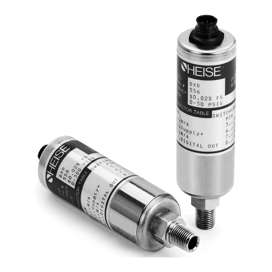
DXD Series
Precision Digital
Pressure Transducer
Operation and
Maintenance Manual
SECTION 1.
Part 1. Installation And Operating Instructions.
Part 2. Command Library And Communication Specification.
SECTION 2.
DXD Setup Utility Manual
i
Advertisement
Chapters
Table of Contents

Summary of Contents for Heisei Electronics DXD Series
- Page 1 DXD Series Precision Digital Pressure Transducer Operation and Maintenance Manual SECTION 1. Part 1. Installation And Operating Instructions. Part 2. Command Library And Communication Specification. SECTION 2. DXD Setup Utility Manual All specifications are subject to change without notice. All sales subject to standard terms and conditions.
-
Page 3: Table Of Contents
TABLE OF CONTENTS SECTION TOPIC PAGE Section 1.0 Introduction ......................3 Section 2.0 Cautions ......................3 Section 3.0 Theory of Operation ...................3 Section 4.0 Unpacking ......................4 Section 4.1 DXD Transducer(s) ....................4 Section 4.2 Certificate of Calibration ..................4 Section 4.3 Utility Software ....................4 Section 4.4 Accessories (RS-232 Configurations only) ............4 Figure 1. - Page 4 COMMAND LIBRARY COMMUNICATION SPECIFICATION TABLE OF CONTENTS (cont.) DXD Firmware Change Summary:..................23-24 Communications Introduction ....................25 Comunications Settings ......................25 Communications Protocol ......................25 Eeprom Lock ..........................26 Command Library Mnemonics ....................26 Unit Address ........................26 Baud Rate ........................27 Eeprom Memory Map Dump ..................27 Error Flag ........................28 Read From Eeprom Address.
-
Page 5: Section 1.0 Introduction
SECTION 1.0 INTRODUCTION Congratulations on your purchase of a DXD Series Digital Pres- sure Transducer. This transducer provides unmatched perfor- mance and value. Innovative modeling and processing firmware assures extremely high precision over a broad temperature range as well as extremely fast response. Please read the following cautions and instructions carefully in order to take full advantage of the product’s capabilities. -
Page 6: Section 4.0 Unpacking
SECTION 4.0 UNPACKING Please note: When handling connectors care should be used to avoid electrostatic discharge to prevent damage to the electronics. The power pins are reverse polarity protected. Use caution if fabricating connector and cable assemblies because the digital I/O lines are not protected from the inad- vertent application of power. -
Page 7: Section 4.4.3 25 To 9 Pin Adapter
SECTION 4.42 SERIAL PORT CONVERTER The Serial Port Converter consists of electronics housed in a standard DB25 enclosure assembly. It has a standard DB25 female RS-232 socket on one end and two RJ11/4 jacks on the other. The DB25 side plugs into a standard 9 pin to 25 Pin Converter or into a USB-RS-232 Adapter. -
Page 8: Section 4.4.6 Limitations Of The Dxd W/Usb Option
SECTION 4.46 LIMITATIONS OF THE DXD W/ Note that for DXD units with the USB interface, only the USB OPTION provided USB cable is required for operation, as all power is provided through the cable. Each DXD will require its own USB port on the PC or a powered HUB (not available through ASHCROFT Inc.) Due to the limitations of the existing utility provided by... -
Page 9: Section 5.2.4 Cable Length And Transmission Speed (Rs-232 & Rs-485)
using a software utility capable of addressing more than one DXD w/USB at a time (note limitations of the Ashcroft Sup- plied Utility in section 4.6). Use powered hubs if the host sys- tem’s power requirements are not adequate for total number of DXD transducers on the network. - Page 10 Table 1. Switchcraft EN3 Pin Assignment for RS-232 Configuration Solder Cup View “SWITCHCRAFT” CONNECTOR PIN *PIN FUNCTION FOR I.D. RS-232 APPLICATION SUPPLY (+) DIGITAL OUTPUT DIGITAL INPUT SUPPLY COMMON *IMPORTANT REQUIRES USE OF SERIAL PORT CONVERTER (#838X003) FOR RS-232 FUNCTIONALITY POSITION #8 NO PIN IN THIS POSITION FOR VENTED CONNECTOR...
-
Page 11: Section 5.4 Wiring Installation For Rs-485 Systems
Table 3. RJ11 Connector Functions for RS-232 Systems DXD DEFINITION “ITT CANNON” “SWITCHCRAFT” CONNECTOR PIN CONNECTOR PIN FUNCTIONS FOR I.D. I.D. HOST DESTINATION WIRE COLOR RS-232 APPLICATION – – RJ11 PLUG BLACK – – DIGITAL OUTPUT – – DIGITAL INPUT GREEN –... - Page 12 SECTION 5.4 WIRING INSTALLATION FOR Required Equipment (RS-485) RS-485 SYSTEMS (CONT.) Either an RS-485 Card, such as B&B Electronics “MIPORT” Isolated PCI Multi-Output Card (model #3PCIOU1), or an RS-485 Adapter (B&B Model USPTL-4) capable of running in full duplex mode is required for setting up an RS-485 system. Connectors: The DXD is supplied with either Switchcraft or Cannon connectors as specified at time of purchase.
- Page 13 Wiring: According to the RS-485 standard, six conductor, shielded, twisted pair 24 AWG wire is recommended for inter- connecting RS-485 systems. However, modular telephone cable (CAT5 or CAT6 rated) and hardware (RJ45 six conduc- tor) can be employed depending on the application (distance, EMI, RFI, speed).
-
Page 14: Section 5.4.1 Pin Functions And Cable Fabrication For Rs-485 Compatible Systems
SECTION 5.4.1 PIN FUNCTIONS & CABLE Various cable components are available from the factory for FABRICATION FOR RS-485 assembling an RS-485 network. Shown below are ‘Y’Splitters COMPATIBLE SYSTEMS for either plastic Switchcraft (838D023-01) or metallic (ITT Cannon (838D024-01) connectors. (Cannon) type connectors. 838D024-01 Ashcroft P/N 831X015-03,... - Page 15 SECTION 5.5 USB APPLICATIONS (CONT.) RS-485 SCHEMATIC DIAGRAM 9 PIN FEMALE “D”-TYPE CONNECTOR MODULAR ADAPTER D89 FEMALE TO RJ45 JACK RJ45 3 4 5 6 JACK RJ45 TO RJ45 CABLE TWISTED PARS 1-2, 3-6, 4-5, 7-8 1 2 3 4 5 6 7 8 “BENDIX”...
-
Page 16: Section 6.0 Installing And Running Utility Software
SECTION 6.0 INSTALLING AND RUNNING Computer Requirements: Any PC capable of running Win- UTILITY SOFTWARE dows XP, or Win7 or Win10™ can be used. Software: A data stick (flash drive) is available for the DXD transducer that provides an easy means of setting up the user configurable features of the DXD along with data logging and display capabilities, also avilable for download on our web site. -
Page 17: Section 7.2 Basic Communications With The Dxd
5. Next you will be prompted for Com Port setup which SECTION 7.1 CONFIGURING HyperTerminal™ should be configured as follows: (CONT.) Bits Per Second 19200 Data Bits Parity Even Stop Bits Flow Contro None 6. Next click on the Settings tab and click the ASCII Setup button. -
Page 18: Section 7.4.2 Determine And Set Baud Rate
The address of the DXD is user configurable and the factory SECTION 7.4.1 DETERMINE AND SET THE default value is 01. CURRENT ADDRESS (CONT.) Note: There may be circumstances where the address of a DXD is unknown. To simplify the task of determining the current address setting, the DXD can recognize a “wild card”... -
Page 19: Section 7.4.3 Determine The Pressure Type
from the “Bits per Second” pull-down. Click OK to close. Finally click OK to close the Properties Dialog. 11. To read the revised baud rate, type the following com- mand: #01BR[CR] 12. The DXD will respond with the following message: BR=19200 1. -
Page 20: Section 8.0 Field Calibration
SECTION 8.0 FIELD CALIBRATION Calibration adjustments on the DXD are limited to zero and span. A high precision primary standard (50 ppm or better) is required for the span adjustment on gauge, vacuum and compound pressure types and a precision absolute standard is required for absolute pressure types. -
Page 21: Section 9.1 Communication Settings
SECTION 9.0 DXD COMMAND LIBRARY to ensure that only one unit is being addressed. To avoid (CONT.) problems that may arise from its use, wildcard addressing should only be used primarily for testing or troubleshooting purposes. Commands issued to a DXD unit can be classified as one of two types. -
Page 22: Section 10.0 Dxd Product Specifications
SECTION 10.0 DXD PRODUCT SPECIFICATION Accuracy: ±0.02% F.S. total error band from 10° - 30°C (50° - 86°F) ±0.04% F.S. 0° - 50°C (32° - 122°F) ±0.05% F.S. -10° - 70°C (14° - 176°F) Temperature Effects: Corrected: -10 to 70°C (14 - 158°F) Operating: -10 to 70°C (14 - 158°F) Storage: -40 to 80°C (-40 - 176°F) Update Rate: from 12.6 mS or 27.7 mS processing time, for... - Page 23 User Accessible Features: Address BPS select Zero Span Tare Pressure Type (G,A,V,C) User Label Error Flag Wild Card Address PSI Reading Serial Number A/D Filter Full Scale Value Firmware Revision I.D. GENERAL DIMENSIONS (INCHES) ITT Cannon KPT107 Switchcraft EN3 (Bendix PT07, PT06 Compatible) 1.500 DIA.
- Page 24 PAGE INTENTIONALLY BLANK COMMAND LIBRARY COMMUNICATION SPECIFICATION DXD Firmware Change Summary:.....................23 Comunication Introduction ......................25 Comunications Settings ......................25 Communications Protocol ......................25 Eeprom Lock ..........................26 Command Library Mnemonics ....................26 Unit Address ........................26 Baud Rate ........................27 Eeprom Memory Map Dump ..................27 Error Flag ........................28 Read From Eeprom Address.
-
Page 25: Dxd Firmware Change Summary
DXD FIRMWARE CHANGE SUMMARY The major firmware enhancements from Firmware Version 2.15 to Version 3.23 firmware for the DXD are listed below for reference. Page references pertain to the detailed operational specifications for the DXD. 1. Alternate Engineering Units (AEU) were added to the com- mand set. - Page 26 8b. Note that Rev. 2.15 firmware does not utilize a decimal point for these ranges, however, all 6000 and 7500 psi range units, in the field, have Rev. 3.23 firmware or higher. This negates any concern of incompatibility. 9. us “user span” write function This command string now requires the addition of a “sign”...
-
Page 27: Communications Introduction
COMMUNICATION INTRODUCTION The DXD Digital Pressure Transducer uses a simple ASCII character based string transmission for communications. A DXD Unit cannot initiate this communication process. A “HOST DEVICE”, i.e. a computer or terminal device must be used to initiate communications by querying the DXD Unit. -
Page 28: Eeprom Lock
EEPROM LOCK A value of “000” written to EEProm location 127, places the EEProm in a LOCKED state. In this state certain commands are disabled and most EEProm locations are set to a READ ONLY state. To disable this “LOCK”, a value of “093” must be written to EEProm location 127. -
Page 29: Br Baud Rate
Important Information: Valid Address values for writing to DXD transducers are: 2-digit values 01 through 99. BAUD RATE Command Description Reads or writes the DXD Unit’s Bits Per Second Rate Command Type READ Command Read Command Syntax #01BR[CR] Typical Read Command Response: Outputs the Bits Per Second Rate as a 12-Character string as shown below Char. -
Page 30: Ef Error Flag
READ ERROR FLAG Command Description Requests the error status byte consisting of 8 flags Command Type Read only Read Command Syntax #01EF[CR] Typical Read Command Response: Char. Position Response Char. ACK CR Typical Read Command Response: Char. Position Response Char. NAK CR This represents Err 03 bad command or bad value. -
Page 31: Ez Eeprom Zero (Initialize Eeprom)
IMPORTANT NOTE: This command automatically verifies the characters written and sends them back. Valid values for writing to the EEPROM using the “ew” command are 3 char- acter decimal values, 000 through 255. IMPORTANT!!! USE OF THE “ez” COMMAND WILL RE-INITIALIZE THE EEPROM TO ITS PRE-CALIBRATION STATE, ALL COEFFI- CIENTS WILL BE LOST . -
Page 32: Fb Filter Band
Command Description Writes the filter amount to EEProm Command Type Dual (READ/WRITE) Command Write Command Syntax #01fa05[CR] Only 01, 02, 03, 04, 05 is accepted. If an invalid FA number is detected in EEProm, then FA=1 is set as a default.This is similar to the detection of an invalid baud rate, Typical Write Command Response: fixed length... -
Page 33: Fv Firmware Version
FIRMWARE VERSION Command Description Returns the unit’s current Firmware version Command Type READ Only Command Read Command Syntax #01FV[CR] Typical Read Command Response: Outputs the Firmware Version as a fixed length 8 character string as shown below. Char. Position Response Char. ACK CR FV Typical Read Command Response HEISE LABEL (SERIAL NUMBER) -
Page 34: Rc Raw Counts
RAW COUNTS Command Description Returns the unit’s raw ADC values, calculated temperature signal and the corrected pressure and temperature values. Command Type READ Only Command Read Command Syntax #01RC[CR] Typical Read Command Response Outputs the Raw Counts as a fixed length 55-Character string as shown below. -
Page 35: Us User Span
USER SPAN Command Description Reads or writes the DXD Unit’s User Span Value Command Type READ Command Read Command Syntax #01US[CR] Typical Read Command Response: Outputs the User Span value as a fixed length 14 character string as shown below. Char. -
Page 36: Uz User Zero
USER ZERO Command Description Reads or writes the DXD Unit’s User Zero Value Command Type Dual (READ/WRITE) Command Read Command Syntax #01UZ[CR] Typical Read Command Response: Outputs the User Zero value as a fixed length 14 character string as shown below. Char. -
Page 37: Fw Feet Sea Water Reading
FEET OF SEA WATER READING Command Description Returns the unit’s current pressure reading in Feet of Sea Water Command Type READ Only Command Read Command Syntax #01FW[CR] Typical Read Command Response: Outputs the feet sea of water reading as a fixed length 14 character string as shown below Char. -
Page 38: Kp Kilopascal Reading
KILOPASCALS READING Command Description Returns the unit’s current pressure reading in Kilopascals Command Type READ Only Command Read Command Syntax #01KP[CR] Typical Read Command Response: Outputs the Kilopascal reading as a fixed length 14 character string as shown below Char. Position Response Char. -
Page 39: Transducer Command Summary
READ COMMANDS SUMMARY Cmd. Description Syntax Response Response (ACK/NAK mode) (AN mode) Read Address #01AD[CR] AD=01[ACK][CR][LF] AD=01 A [CR][LF] Bit Per Second Rate #01BR[CR] BR=19200[ACK][CR][LF] BR=19200 A [CR][LF] EEPROM Dump #01ED[CR] 1st 160 Bytes of EEPROM mem 1st 160 Bytes of EEPROM mem Error Flag #01EF[CR] 00000000[ACK][CR][LF]... -
Page 40: Aeu Command Summary
ERROR CODES SUMMARY The DXD Transducer will return error codes if operating in “LEGACY mode” rather than a “nak” or “N”, for example where a user issues an incorrect command syntax, and when measurement values are out of specifications due to sensor damage, electrical problems etc. - Page 41 Bit positions 0 No A/D self calibration 1 A/N appended to response 2 <cr> <lf> if appended after ACK/NAK 3 no echo 4 DXD Command set 5 Error Status Character on 7 no noise test Bit positions 0 No A/D self- calibration 1 A/N appended to response 2 <cr>...
-
Page 42: Detailed Explanation Of The "Fa" & "Fb" Commands
using the “ew” command, a three digit value with leading zeros is required. Examples: DXD Firmware V3.xx 0000000 no calibration, ACK/NAK appended to response, <cr> < lf> appended after ACK/ NAK, no echo, DXD Command set, Error Status Char. On, no noise test. 00000010 same as above, only A/N appended instead of ACK/NAK 002... - Page 43 Command: #01fa05[cr] To confirm the change, re-send the initial Read Command. FB (Filter Band) The filter band determines whether or not filtering is taking place and what percentage of the pressure span is being filtered (by the amount set in FA). Filtering is disabled if a pressure transient exceeds the value set for FB.
-
Page 44: Alternate Engineering Units (Aeu) Explained
ALTERNATE ENGINEERING UNITS (AEU) EXPLAINED The following table shows the relationship between pressure in psi and pressure displayed in the available alternate engi- neering units in the DXD. Note that at pressures above zero it is possible for a selected engineering unit to display well over the normal 50,000 count limit defined for the DXD. - Page 45 ms. in increments of 5 ms. The “Total update time” column (under mili seconds) represents updates which include transmit and receive communications for a “PS” command at 115.2 K baud. The column to the right of that represents update rates without any communication time factored in. To find the actual turn-around time of command, update, and a response, use the last column for the A/D update time, and add the transmit and receive time required, based upon the...
-
Page 46: Synchronous Read Command (Addendum A)
Addendum A SYNCHRONOUS READ (Sr) Command Specifications for DXD Firmware Revision 3.31 & Higher The DXD “Synchronous Read” command structure is defined to be a series of two or more commands, depending upon the number of units on the serial bus. The process begins with the host computer sending the GLOBAL command “#**Sr”. -
Page 47: Read Commands Summary
NOTE: Numbers in parentheses after commands are the reponnse times of the transducer to that particular command. SYNCHRONOUS READ INITIALIZE COMMAND Command Description Syntax Response Response (ACK/NAK mode) (A/N mode) Start Synchronous Read #**Sr BLIND RESPONSE BLIND RESPONSE SYNCHRONOUS AEU COMMANDS SUMMARY Command Description Syntax... -
Page 48: Ats Varient (Addendum B)
ADDENDUM B DXD ____ ATS VARIANT DEFINITION Data Structure; 8 data bits 7 data bits 1 Stop bit 1 stop bit No Parity bit Even parity This data structure will be turned on and off using the mode byte in eeprom at address location 001. Bit 4 of this byte will define the data format. - Page 49 6. #01taCODE+000.000cr (Write a user TARE value) a. There is no response string to this command. b. CODE is a 4 digit access code that the ATS required for certain operations. In this case the access code will be always defaulted to “CODE”. c.
-
Page 50: Dxd Receiver To Transmit Delay Capabilities (Allows Half Duplex Operation In Rs-485)
1, The 11 ASCII spaces are stuffed to simulate the expected response from an ATS, 17 characters including the carriage return. #01br1200cr Change the baud rate of the DXD #01br2400cr #01br4800cr #01br9600cr #01br19200cr #01br38400cr #01br57600cr #01br115200cr 1, There is no response string to this command. 2, This is the same command as in standard DXD except that the baud rate selections differ. - Page 51 PAGE INTENTIONALLY BLANK...
- Page 52 For the name and location of the nearest sales representative, contact the Stratford sales office. World Headquarters Ashcroft Inc. 250 E. Main Street Stratford, CT 06614-5145 U.S.A. Tel: (203) 378-8281 Fax: (203) 385-0402 (Domestic) Fax: (203) 385-0357 (International) email: info@heise.com www.heise.com Visit our web site at www.heise.com All specifications are subject to change without notice.
-
Page 53: Ascii Character Code Table (Page 26 Of Installation And Operation Instructions) Dxd Set-Up Utility, Manual/Software
DXD Setup Utility User Manual All specifications are subject to change without notice. All sales subject to standard terms and conditions. © 2016 Ashcroft Inc.10/16 I&M002-10107... - Page 55 TABLE OF CONTENTS SECTION TOPIC PAGE About This Manual ....................54 Scope ........................54 Purpose ........................54 Intended Audience....................54 Notation Conventions ....................54 Getting Started ......................54 Installing the Utility via the Data Stick ..............54 DXD w/ USB interface, Communications Setup ............54 If the DXD w/USB Fails to Enumerate ..............
-
Page 56: About This Manual
SECTION 1.0 ABOUT THIS MANUAL SECTION 1.1 SCOPE This manual explains the features and use of the Ashcroft Instruments DXD Setup Utility. Although operation of the Ashcroft Instruments DXD Setup SECTION 1.2 PURPOSE Utility is intuitive, this manual provides more definition to enhance its use. -
Page 57: If The Dxd W/Usb Fails To Enumerate
Utility” software, unlike with RS-232 or RS-485, only one DXD w/ USB can be addressed at a time. In this case, the utility is used to set up the DXD for use with other software supplied by the end user. 1, If the correct driver for the interface IC inside the DXD doesn’t reside on the user’s system it will be necessary SECTION 2.3... -
Page 58: Keyboard Navigation
Use the <Enter> key to select a highlighted menu item or SECTION 2.5.3 KEYBOARD NAVIGATION accept the value of a control. Use the <Tab> key to step through selection of each of the controls on the window. When a list type control is selected, use the up and down arrow keys to scroll through the selections. - Page 59 SECTION 2.6 MENUS (CONT.) Figure 5 The Monitor menu choices include Find, Normal Speed, and High Speed as shown in Figure 6. The Find selection opens a window for searching the specified port for connected transducers. The Normal Speed selection opens a window for monitoring 1 to 99 transducers (RS-232 or RS-485 for multiple transducers only, single USB only communication available ), at a rate no faster than four samples/second, on...
-
Page 60: Operation
DXD pressure transducers to your computer for use with the DXD Setup Utility software, please consult with the DXD Series – Precision Digital Pressure Transducer Instal- lation and Operating Instructions. When connecting new transducers for the first time, connect one at a time until each is configured with a unique address, and communication properties are configured. -
Page 61: Port
Figure 9 SECTION 3.1.1 PORT The port identifies the serial communications port to which the DXD pressure transducer(s) is(are) connected. To find available ports, navigate to the Device Manager in windows…, and expand the Ports (COM & LPT) item. Available choices for port are 1-256. -
Page 62: Normal Speed Monitor
SECTION 3.2 FIND (CONT.) The current communication properties are shown at the bottom right of the window. They are shown in order of com- munication port (COM1), baud rate (115200), parity (Even), number of data bits (7), and number of stop bits (1). Select the “Type of Search,”... -
Page 63: Selection Of Pressure Transducer And Pressure Units
SECTION 3.3 MONITOR>>NORMAL SPEED (CONT.) Figure 11 SECTION 3.3.1 SELECTION OF PRESSURE To monitor a single transducer or multiple transducers on the TRANSDUCER AND PRESSURE table, first enter the address in the “DXD Address” control, select UNITS the desired “Pressure Units” in the same named control, and click the “Add Unit”... -
Page 64: Logging
SECTION 3.3.2 MONITOR (CONT.) Figure 13 shows an example of the gauge indicator. The pressure of the DXD pressure transducer specified by the “DXD Address” control is shown here with the selected “Pressure Units.” The “Add Unit” and “Remove Unit” con- trols are disabled when monitoring pressure on the gauge indicator because only one pressure can be shown on this indicator. -
Page 65: Calibration
The instructions for manually performing these tasks is contained in the DXD Series – Precision Digital Pressure Transducer Installation and Operating Instructions. SECTION 3.3.4.1... -
Page 66: High Speed Monitor
control, and then click the “Set Span” button. A dialog will prompt to confirm the selection. NOTE: The pressure standard MUST have an accuracy of at least .005% of the full scale value of the DXD being cali- brated to maintain advertised accuracy of the DXD. Gauge or Digital Indicator: Select the address of the trans- ducer to which the span should be applied via the “DXD Address”... -
Page 67: Selection Of Pressure Transducer And Pressure Units
SECTION 3.4.1 SELECTION OF PRESSURE To view the pressure trend for a trans- TRANSDUCER AND PRESSURE ducer, enter the address in the “DXD UNITS Address” control and select the desired “Pressure Units” in the same named con- trol. Valid addresses are 01 through 99, and addresses must be unique when DXD pressure transducers are daisy-chained. -
Page 68: Utility Diagnostics
Figure 16 NOTE: To keep a copy of the “as received” eeprom data it is SECTION 3.5 UTILITY>>DIAGNOSTICS recommended that the user use this utility to first READ the contents of the DXD eeprom using the “Get Settings” com- mand and then SAVE the contents to a file on the controlling computer using the “Save Settings”... -
Page 69: Utility Command And Query
Figure 17 SECTION 3.6 UTILITY COMMAND AND QUERY This window, shown in Figure 18, provides the lowest level (closest to the driver) functionality for writing and reading commands to and from a DXD pressure transducer in an easy-to-use format. The current communication properties are shown at the bottom right of the window. -
Page 70: Read Commands
“Response String” indicator. The {ASCII String} “Command” selection can also be used to write a value to the DXD pres- sure transducer. Reference the DXD Series – Precision Digital Pressure Transducer Communications Specification. When this selection is made, the “ASCII Command String” control shows to the right of the “Command”... -
Page 71: Files
In DXD-mode an error byte must be read imme- diately after a command is sent to the DXD. Please reference the DXD Series precision digital pressure transducer opera- tion and maintenance manual for detailed definitions of both the ATS Legacy error codes and the DXD error byte bits. -
Page 72: High Speed Data File
SECTION 4.2 HIGH SPEED DATA FILE Figure 20 shows a typical high-speed data file. This is the type of file created when logging on the high-speed monitor screen as described in Section 3.4.2. There are always two columns in this file because only one pressure transducer is monitored at a time on the high-speed monitor screen. - Page 74 For the name and location of the nearest sales representative, contact the Stratford sales office. World Headquarters Ashcroft Inc. 250 E. Main Street Stratford, CT 06614-5145 U.S.A. Tel: (203) 378-8281 Fax: (203) 385-0402 (Domestic) Fax: (203) 385-0357 (International) email: info@heise.com www.heise.com Visit our web site at www.heise.com All specifications are subject to change without notice.
Need help?
Do you have a question about the DXD Series and is the answer not in the manual?
Questions and answers