
Related Manuals for Yenista Optics TUNICS T100S-HP

Summary of Contents for Yenista Optics TUNICS T100S-HP
- Page 1 TUNICS T100S-HP High Power Tunable Laser User Manual TUNICS-T100SHP_UM_6.04v1.9...
-
Page 3: Legal Notice
No Warranties: This documentation is provided "as is" without any ex-touch or implied warranty of any kind. Limitation of Liability: Yenista Optics does not assume any liability arising out of the application or use of any products, or software described herein. In no event shall Yenista Optics or its affiliate companies be liable for any damages whatsoever (including, without limitation, consequential or incidental damages, damages for loss of profits, or otherwise) arising out of the use of the information provided in this documentation. -
Page 4: Contact Information
Phone: +86 21 5160 7615 Customer Support and Repair Services Americas Europe, Middle East and Africa Email: support-am@yenista.com Email: support-emea@yenista.com Phone: +1 805 367 4075 Phone: +33 296 486 145 China Asia and Pacific Email: support-china@yenista.com Email: support-apac@yenista.com TUNICS T100S-HP User Manual... -
Page 5: About This Manual
About This Manual Subject This manual explains how to install, set-up and use the TUNICS T100S-HP tunable external cavity laser. It also explains how to perform basic maintenance operations. The remote control of the TUNICS T100S-HP is described in TUNICS T100S-HP Programming Guide. - Page 6 About This Manual TUNICS T100S-HP User Manual...
-
Page 7: Table Of Contents
Description of the Rear Panel ........................18 Installing and Connecting the Product ....................21 Unpacking and Installing the Product........................21 Connecting the TUNICS T100S-HP to a Power Source..................22 Connecting External Optical Devices to the product ..................22 Installing the Remote Interlock ..........................23 Turning on/off and Initializing the Product .................. - Page 8 10.3 Replacing the Line Fuse ..............................56 10.4 Packaging for Shipment..............................56 11. Error and Warning Messages ........................57 Certification and Compliance ......................... 59 List of Tables..............................61 List of Figures ..............................62 Index .................................. 63 TUNICS T100S-HP User Manual...
-
Page 9: Safety Information
(behind the product) are used for the inside ventilation. CAUTION • If you plan to rack-mount this product, make sure to allow at least a 15- mm (0.6 inches) gap between two products. TUNICS T100S-HP User Manual... - Page 10 • The TUNICS T100S-HP has a chassis connected to ground via the power supply cable. A protective ground connection by way of the grounding conductor in the power cord is essential for safe operation.
-
Page 11: Product Presentation
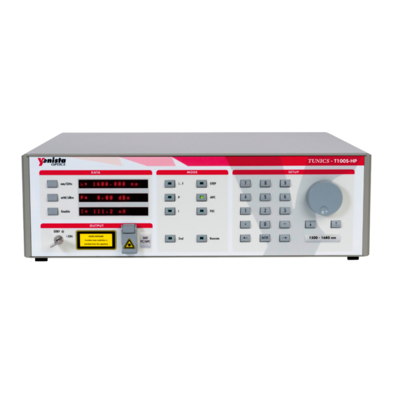
1. Product Presentation Product Features The TUNICS T100S-HP is a high-performance, self-aligned external cavity laser that implements Yenista Optics’ state-of-the-art proprietary configuration. The TUNICS T100S-HP is a general-purpose instrument designed for fiber-optic system testing and precise WDM component testing, as well as for research and development in the field of optical communications. -
Page 12: Technical Specifications
Table 2: TUNICS T100S-HP – Main Features Technical Specifications The following table lists the technical specifications of all TUNICS T100S-HP models. Essential Models Extended Range Models Wavelength range (nm) 1260–1360... -
Page 13: Table 3: Technical Specifications
This location is a typical office/home environment. Temporary condensation occurs only when the product is left unused. Safe operating +10 ˚C to +35 °C (+50 ˚F to +95 °F) temperature range TUNICS T100S-HP User Manual... -
Page 14: Table 4: Environmental Specifications
Time at Each Scan Step 0.1 - 25 sec (Pause Timer) Table 5: Valid Range for Parameter Settings Available Accessories and Replaceable Parts For information about accessories and replaceable parts, contact your Yenista Optics sales representative. Name Description Fuse 4A T 250V... -
Page 15: Product Overview
A USB key containing the user documentation and available software For more information on replaceable parts, see section Available Accessories and Replaceable Parts, p. 14. This section provides an overview of the operating interfaces of all TUNICS T100S-HP functions. 1.3.1... - Page 16 To perform system auto-calibration (see section Performing Internal Wavelength Referencing, p. 38). To disable/enable active cavity control (see section Disabling/ Enabling Active Cavity Control, p. 34). dBm/mW To turn on active wavelength monitoring (see section Enabling Active Wavelength Monitoring, p. 39). TUNICS T100S-HP User Manual...
-
Page 17: Table 8: Mode Area - Function Keys
232 remote mode: see TUNICS T100S-HP Programming Guide. To enable the coherence control function (see section Turning On/Off Coherence Control, p. 32). Remote Switches between remote mode and manual mode (see TUNICS T100S-HP Programming Guide). Table 8: MODE Area – Function Keys SETUP Area Description The SETUP area is used to enter or change the values of the system operating parameters. -
Page 18: Description Of The Rear Panel
Mod. Sync: BNC connector for modulation sync (TTL output). • Mod. Out: BNC connector for modulation output (TTL output). For a detailed description on particular connectors, see section Using the Auxiliary Inputs and Outputs, p. 43. TUNICS T100S-HP User Manual... - Page 19 Outputs, p. 43. Remote Interfaces • RS-232 C remote control (SUBD-9 connector). • GPIB remote control (IEEE-488.1 connector). Remote commands are available in TUNICS T100S-HP Programming Guide. Labels Label Description Identification of the Product SERIAL NUMBER Indicates serial number, model number, options (if any), xxxxxxxxxxxx and date of manufacture.
-
Page 20: Table 10: Rear Panel Labels
The product has an environment friendly use period of 40 years. See section Certification and Compliance, p. 59. Warranty Seal Warranty void The product cover must not be open, otherwise the if seal broken. warranty is not valid anymore. Table 10: Rear Panel Labels TUNICS T100S-HP User Manual... -
Page 21: Installing And Connecting The Product
8. Place the TUNICS T100S-HP in the wanted operating position as illustrated in Figure 3, p. 21. To tilt the TUNICS T100S-HP upward, deploy the two retractable legs located below it. Figure 3: Possible operating positions (bench-top) -
Page 22: Connecting The Tunics T100S-Hp To A Power Source
3. Connect one end of the power supply cable to the rear panel of the product and plug the other end to the proper voltage mains supply point. The TUNICS T100S-HP is equipped with a self-regulating power supply that adapts to both AC 110V and 230V voltages, and 50 Hz or 60 Hz frequencies. -
Page 23: Installing The Remote Interlock
Installing and Connecting the Product Installing the Remote Interlock Subject The TUNICS T100S-HP is equipped with a Remote Interlock connector at the rear-panel. You can connect an external remote interlock switch to the Remote Interlock SUBD-9 connector located on the rear panel. - Page 24 Installing and Connecting the Product TUNICS T100S-HP User Manual...
-
Page 25: Turning On/Off And Initializing The Product
3. Turning on/off and Initializing the Product Initializing the Laser Before Starting If the TUNICS T100S-HP has previously been shut down (see section Shutting Down the Product, p. 26), you must wait at least thirty seconds before initializing the laser again. -
Page 26: Enabling/Disabling The Laser Output
On the third display, the message Disabled is replaced with diode current I. The Enable LED is lit to indicate that the TUNICS T100S-HP is emitting a laser output. 2. To disable the laser output: in the DATA area, press the Enable key again and check that the Enable key LED is off. -
Page 27: Setting Up The Emission Wavelength Or Frequency
The required output power may not be reached even at the maximum allowable current. If this occurs, the TUNICS T100S-HP automatically limits the current to its maximum value and the message "Lim" appears at the right end of the displayed... -
Page 28: Setting A Predefined Increment/Decrement Step
Parameter Settings, p. 14. The required output power may not be reached even at the maximum allowable current. If this occurs, the TUNICS T100S-HP automatically limits the current to its maximum value and the message "Lim" appears 4. In the SETUP area, press the ENTER key. -
Page 29: Implementing Step-By-Step Wavelength Scanning
STEP parameter) up to the last wavelength value (upper wavelength limit that you set). During each scan interval, the TUNICS T100S-HP laser broadcast at a set wavelength for the duration specified by the Pause Timer parameter that you set. - Page 30 8. To stop the scan, press the numeric keys 1 + Enter. Scanning stops and the emission wavelength remains set to the value applied at the time the scan was suspended. 9. To resume scanning, press numeric keys 0 + Enter. TUNICS T100S-HP User Manual...
-
Page 31: Implementing Continuous Wavelength Sweep (Hop-Free)
The DATA area display prompts you to enter the Pause Timer. The PAUSE TIMER is the dwell time at the upper wavelength of the sweep range before the TUNICS T100S-HP tunable laser returns to the lower wavelength to restart a new sweep cycle. -
Page 32: Setting The Sweep Speed
33, 40, 50, 67, 100] (nm/s). Therefore, the speed you select is rounded-up to nearest value of operational speed. For example, if you select a 70 nm/s sweep speed on the TUNICS T100S-HP front panel, your setting is automatically corrected by the system to match the nearest operational value, i.e. -
Page 33: Changing The Optical Output Power And Diode Current
The required output power may not be reached even at the maximum allowable current. If this occurs, the TUNICS T100S-HP automatically limits the current to its maximum value and the message "Lim" appears at the right end of the displayed... -
Page 34: Disabling/Enabling Active Cavity Control
To enable active cavity control, press the 2nd + APC command keys again. If the APC LED starts blinking while the TUNICS T100S-HP is in APC mode with active cavity control on, this may indicate that the laser power output (P) is set to a value lower than the 0.8 mW threshold. -
Page 35: Changing The Laser Diode Current
To modify the basic increment/decrement applied by the rotary knob, press the and ↑ arrow keys to set the scroll step at either 1 mA or 0.1 mA. 3. In the SETUP area, press the ENTER key. TUNICS T100S-HP User Manual... - Page 36 Changing the Optical Output Power and Diode Current TUNICS T100S-HP User Manual...
-
Page 37: Calibrating The Product
6. Measure the power level at the second wavelength. 7. Enter the reading at the prompt P =. The power calibration is now complete and the instructions reference the new power calibration data. TUNICS T100S-HP User Manual... -
Page 38: Performing Internal Wavelength Referencing
Before Starting Make sure the Remote Interlock switch is closed: for laser safety reasons the TUNICS T100S-HP features a Remote Interlock connector at the rear-panel that can connect to an external remote interlock switch. When the interlock switch is open, the laser output is turned off. -
Page 39: Enabling Active Wavelength Monitoring
As an example, with a Burleigh-EXFO wavemeter, use a DB9 male-male straight-through serial cable to connect the TUNICS T100S-HP RS-232 C port to the wavemeter serial port. Please contact your Yenista Optics representative for a list of compatible wavemeters. -
Page 40: Figure 6: Instrument Setup For Wavelength Monitoring
Enabling Active Wavelength Monitoring Procedure 1. To setup the measurement, connect the TUNICS T100S-HP output to the wavemeter via the low output port of an optical coupler. The remainder of the signal available on the coupler’s high-output is sent to the component under test, as shown in the following figure. -
Page 41: Performing Wavelength Monitoring
1.5 s to 2 s. The following procedure explains how to perform wavelength monitoring of the TUNICS T100S-HP using a wavemeter. Procedure 1. Configure the wavemeter remote interface with the following parameters: •... - Page 42 Enabling Active Wavelength Monitoring 2. Connect the TUNICS T100S-HP DB9 serial port to the wavemeter serial port. 3. As the tunable laser acts as the controller device for the wavemeter, press the 2nd+Remote function keys at the TUNICS T100S-HP front-panel and select: RS-232 IN: [OFF] 4.
-
Page 43: Using The Auxiliary Inputs And Outputs
8. Using the Auxiliary Inputs and Outputs The auxiliary input and output connectors are located on the rear panel of the TUNICS T100S-HP, as described in section Description of the Rear Panel, p. 18. Implementing External Modulation 8.1.1 Implementing Low Frequency Intensity Modulation... -
Page 44: Figure 8: Low Frequency Modulation Setup
Using the Auxiliary Inputs and Outputs • Make sure to use a 50 Ω BNC cord to connect the TUNICS T100S-HP and the waveform generator. TUNICS T100S-HP Laser Diode Source LF Mod. BNC Connector LF Modulation Circuit bias Polarization Current... -
Page 45: Figure 9: Resulting Lf-Modulated Diode Current
1 kHz) of the APC loop, the average power is monitored, and remains constant. Modulation is possible in the APC mode at frequencies above 30 kHz. If a lower frequency is used, interaction between modulation signal and APC circuit will cause unpredictable modifications of the output power waveform. TUNICS T100S-HP User Manual... -
Page 46: Implementing High Frequency Intensity Modulation
Figure 10, p. 46. Make sure to use a 50 Ω coaxial cord to connect your HF generator to the 50 input SMA connector. TUNICS T100S-HP Laser Diode Source HF Mod. SMA Connector internal Ω... -
Page 47: Figure 11: Resulting Hf-Modulated Diode Current
• is the voltage applied to the HF Mod input • is the50 Ω internal resistor of your TUNICS T100S-HP internal By modulating this extra current, the optical power output can be modulated within a frequency range from 30 kHz to 200 MHz. The low-frequency cutoff is 30 kHz. The modulation bandwidth is greater than 200 MHz, and this HF Mod input can also be used for mode-locked operation. -
Page 48: Wavelength Modulation
(see section Disabling/Enabling Active Cavity Control, p. 34). Wavelength Fine The TUNICS T100S-HP has a wavelength fine tuning capability that can be used to adjust Scanning the wavelength very precisely, or to serve the optical frequency. -
Page 49: Output Signals
8.2.3 Activating/Deactivating the λ Output as a Trigger Subject You can switch the λ output to a trigger (TTL) that is high when the TUNICS T100S-HP is scanning (only in positive direction ignoring return and backlash). Procedure 1. Press the 2nd + 3 keys. - Page 50 Using the Auxiliary Inputs and Outputs TUNICS T100S-HP User Manual...
-
Page 51: Verifying Performances
Table 13: Test Equipment Procedure 1. Warm up the TUNICS T100S-HP tunable laser under test and the test equipment for 2 hours at an ambient temperature (between 20° and 30° C). 2. Initialize the system as described in section Initializing the Laser, p. 25. -
Page 52: Verifying The Absolute Wavelength Accuracy
3. Set the wavelength of the tunable laser to the lower limit of the wavelength range according to the TUNICS T100S-HP model (see section Technical Specifications, p. 12). 4. Enable the laser output and verify the wavelength at the lower limit ±0.04 nm. -
Page 53: Verifying Side Mode Suppression
If the performance does not meet warranted specifications, a complete calibration of the product may be required. Some calibration steps require the adjustment of internal components including the laser head. Therefore, a complete calibration must be performed by authorized Yenista Optics staff only. TUNICS T100S-HP User Manual... - Page 54 Verifying Performances TUNICS T100S-HP User Manual...
-
Page 55: 10. Performing Basic Maintenance Operations
10. Performing Basic Maintenance Operations User maintenance of the TUNICS T100S-HP is limited to the following: • Cleaning optical connectors for optimum power • Checking the performance of optical connections and cables • User calibration (see section Calibrating the Product, p. 37) •... -
Page 56: Cleaning The Product
3. Replace the fuse in the fuse holder and snap the fuse holder back into the lined filter. 10.4 Packaging for Shipment If you need to return the TUNICS T100S-HP to Yenista Optics for servicing or calibration, use the original packaging. For instructions on returning the instrument, please contact Yenista Optics (see section Contact Information, p. -
Page 57: 11. Error And Warning Messages
Message Possible Cause Troubleshooting WARNING: User calibration is As the user calibration is not valid, the TUNICS T100S-HP implements User calib. Err press "enter" not correct. the default calibration value instead. ERROR: No factory calibration. Turn off the system and check the integrity of electrical connections. -
Page 58: Table 14: Error And Warning Messages
The temperature of the room is Switch off the product and make too high, the laser is disabled sure the temperature room is lower Laser Head than 30°C before starting again the Overheating product. Table 14: Error and Warning Messages TUNICS T100S-HP User Manual... -
Page 59: Certification And Compliance
In all cases, should you require Yenista Optics to arrange such take back and disposal, please contact your local Yenista Optics representative. This obligation will be met by Yenista Optics for any equipment that is sold by Yenista Optics in the EU area irrespective of how many times it has been sold on. - Page 60 Certification and Compliance TUNICS T100S-HP User Manual...
-
Page 61: List Of Tables
List of Tables Table 1: Safety Labels and Symbols ..............................9 Table 2: TUNICS T100S-HP – Main Features ..........................12 Table 3: Technical Specifications ..............................13 Table 4: Environmental Specifications ............................14 Table 5: Valid Range for Parameter Settings ..........................14 Table 6: Available Accessories and Replaceable Parts ......................14 Table 7: DATA Area –... -
Page 62: List Of Figures
Figure 6: Instrument Setup for Wavelength Monitoring ......................40 Figure 7: Wavelength Monitoring Scheme ..........................41 Figure 8: Low frequency modulation setup ..........................44 Figure 9: Resulting LF-modulated diode current ........................45 Figure 10: High frequency modulation setup ..........................46 Figure 11: Resulting HF-modulated diode current ........................47 TUNICS T100S-HP User Manual... -
Page 63: Index
Wavelength calibration ........38 CE Marking ................59 China RoHS Directive ............59 GPIB Connector ...............19 Cleaning ................55 Coherence Control HF Mod input ..............19 Enable/Disable ............32 High Frequency Modulation ........46 Input ................48 Hop-free ................31 Compliance ...............59 TUNICS T100S-HP User Manual... - Page 64 ..............15 Step-Mode Wavelength Scanning ......29 Numeric keypad ..............17 Stop scan ................30 SUBD-9 connector ..........19 Sweep ................. 31 Operating mode Sync. output ..............18 Constant-current mode ........16 Synchronization signal ..........49 Constant-power mode ........16 TUNICS T100S-HP User Manual...
- Page 65 TTL outputs ............... 18 Modulation .............. 48 Monitoring ............... 39 Range verification ..........52 Units ..................15 Sweep ................. 31 Wavemeter use ............... 39 WEEE ................... 59 Valid range ................14 Verification ................51 λ λ output ..............18 λ.f key ................. 16 TUNICS T100S-HP User Manual...
- Page 66 Index TUNICS T100S-HP User Manual...
Need help?
Do you have a question about the TUNICS T100S-HP and is the answer not in the manual?
Questions and answers