Force Flow WIZARD 4000 Operation & Maintenance Manual
Digital weight indicator
1 to 4 channels
Hide thumbs
Also See for WIZARD 4000:
- Installation & operation manual (40 pages) ,
- Installation & operation manual (47 pages)
Table of Contents
Advertisement
WIZARD 4000
DIGITAL WEIGHT INDICATOR
1 to 4 Channels
#3 NET 57.11 GL
#3 BULK 0.0 GL
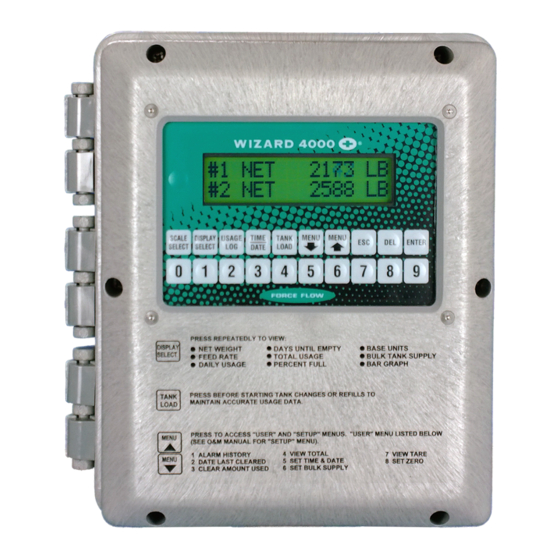
PRESS REPEATEDLY TO VIEW:
NET WEIGHT
DAYS UNTIL EMPTY
BASE UNITS
FEED RATE
TOTAL USAGE
BULK TANK SUPPLY
DAILY USAGE
PERCENT FULL
BAR GRAPH
PRESS BEFORE STARTING TANK CHANGES OR REFILLS TO
MAINTAIN ACCURATE USAGE DATA.
ACCESS "USER" AND "SETUP" MENUS. "USER" MENU LISTED
BELOW (SEE O&M MANUAL FOR "SETUP" MENU).
1 ALARM HISTORY
4 VIEW TOTAL
7 VIEW TARE
2 DATE LAST CLEARED
5 SET TIME & DATE
8 DISPLAY UNITS
3 CLEAR AMOUNT USED
6 VIEW BULK SUPPLY
9 SET ZER
2430 Stanwell Dr, Concord, CA 94520 USA
1-800-893-6723 US & Canada, Fax: 925-686-6713
www.forceflow.com / info@forceflow.com
Advertisement
Table of Contents

Related Manuals for Force Flow WIZARD 4000


Summary of Contents for Force Flow WIZARD 4000
- Page 1 WIZARD 4000 DIGITAL WEIGHT INDICATOR 1 to 4 Channels #3 NET 57.11 GL #3 BULK 0.0 GL PRESS REPEATEDLY TO VIEW: NET WEIGHT DAYS UNTIL EMPTY BASE UNITS FEED RATE TOTAL USAGE BULK TANK SUPPLY DAILY USAGE PERCENT FULL BAR GRAPH PRESS BEFORE STARTING TANK CHANGES OR REFILLS TO MAINTAIN ACCURATE USAGE DATA.
- Page 2 INDEX SECTION II WIZARD 4000 WEIGHT INDICATOR INDEX INSTALLATION CHECKLIST START-UP CHECKLIST KEYBOARD QUICK REFERENCE GUIDE (Drawing 30835) ELECTRONIC INDICATOR SPECS (Drawing 30831) KEYPAD FUNCTIONS TANK LOAD PROCEDURE (Drawing 30774) HAZARDOUS LOCATION INSTALLATION (Drawing 29893) WIRING INSTRUCTIONS (Drawing 29892) W.10 MOTHERBOARD COMPONENT LAYOUT INSTALLATION &...
-
Page 3: Installation Checklist
WIZARD 4000 INDICATOR INSTALLATION CHECKLIST INSTALL SCALE PLATFORM(S), PROCELL(S) or ECHO-SCALE(S) in accordance with supplied Operation & Maintenance Manual. MOUNT INDICATOR WIRE INDICATOR FORMAT INDICATOR (See Pages W.4 through WA-16) Check all current settings in USER and SETUP Menus.. Make changes as needed for your specific application. -
Page 4: Start-Up Checklist
WIZARD 4000 INDICATOR START-UP CHECKLIST POWER-UP: Scale display should read NET WT or NET REMAINING. Press DISPLAY SELECT key as needed until display reads NET WT or NET REMAINING. SCALE APPLICATIONS: Apply weight (press on platform or tank) and verify indicator NET WT responds. - Page 5 KEYBOARD QUICK REFERENCE GUIDE These are the functions that are used on a day-to-day basis. SCALE SELECT Scrolls forward through individual scales. DISPLAY SELECT Toggles through a multi-function display for each scale in the following decending order: 1 NET REMAINING.... Chemical remaining in tank or cylinder (default screen) Analog bar graph.
-
Page 6: Specifications
OPTIONS: MODELS: JOB REFERENCE: _______________________________________/s/___________ SUBMITTAL DATA: Wizard 4000 Model No.___________________ 4000-1 (1-Channel) 4-20mA OUTPUT SIGNALS (Model WMA420): Up to 8 separate output signals (NET, RATE, DAILY, BULK or TOTALS) 4000-2 (2-Channel) INPUTS No. of Channels _____________ 1000 ohms max per output. -
Page 7: Keypad Functions
Release "DEL" key. "YES * NO" Press "MENU" arrow keys to choose "NO" ENTER SCALE # Press "MENU" arrow keys to choose different WIZARD 4000 + number than you did before. #3 NET 57.11 GL #3 BULK 0.0 GL Data Entry Toggles... - Page 8 TANK #2, etc). After entering the tare weights of all your tanks, the LBS = 1234 WIZARD 4000 automatically adds them up and subtracts them from the gross weight. "PERMANENT" Tank Applications (follow Steps 1, 2 and 7 only), such as...
-
Page 9: Hazardous Locations
MEET SAFETY REQUIREMENTS: ENVIRONMENT, PLEASE CONSULT FACTORY FOR SAFETY PRECAUTIONS. FOR FURTHER TECHNICAL INFORMATION OR FOR APPLICATIONS ENGINEERING ASSISTANCE, PLEASE CONTACT FORCE FLOW AT FORCE FLOW AT 925-686-6700; info@forceflow.com OR 1-800-893-6723. WALL Allows refilling of tanks. To maintain accurate usage data, DO NOT fill tanks until STEP 3. - Page 10 COMMUNICATIONS Drawn by: SLP/MD Drawing Number 2430 Stanwell Dr, Concord, CA 94520 USA ® 1-800-893-6723 US & Canada, Fax: 925-686-6713 WIZARD 4000 INDICATOR Date: 09/01/95 www.forceflow.com / info@forceflow.com 29893 WIRING REFERENCE Revised: 12/05/06 PR328 File: T4\NEW O&M 2007\W9 WIZ NEW PR328 INDI.tcw...
-
Page 11: Load Cells
4-20mA OUTPUT POWER IN FUSE LOAD CELLS 6" ULTRASONIC RELAYS DISPLAY ANGLE SENSORS ADJUSTMENT (Blue) RS232 (J1) MOUNTING FIXTURE RS485 (J4) WIRE CABLE CLAMP 13" Drawing Number WIZARD 4000 INDICATOR 29892 COMPONENT LAYOUT File: T4\NEW O&M 2007\W10 WIZ NEW PR328 INDIA.tcw... -
Page 12: Power Hook-Up
IF "LOAD CELL" CONNECTION The Wizard 4000 indicator is shipped with the load cell(s) already connected. If routing load cell cable through conduit or trimming cable length, remove cable connector from motherboard, then cable from connector and finally cable from Wizard enclosure. - Page 13 MODBUS SERIAL COMMUNICATION OPTION (OPTION MODEL NO's: WRS232 & WRS485) The Wizard 4000 is provided with a separate 1/2" conduit connector for your serial port communication wiring. DO NOT co-locate inductive load wiring or power lines with communication wiring. Attach your communication wiring per the following:...
-
Page 14: Alarm History
USER MENU (WIZARD 4000) MENU Arrow Keys: There are 2 menus that may be accessed via the "MENU" keys. The "USER" Menu and "SETUP" Menu. The "USER" Menu has 8 menu items, and these are functions that are used for day-to-day operations. -
Page 15: View Total
USER MENU continued... ACTION REQUIRED: DIGITAL DISPLAY: Allows user to view the combined Net, Rate and Usage for more 4 VIEW TOTAL than 1 channel. This function must be configured under the SETUP VIEW TOTAL selection in the SET UP MENU. Allows you Step 1 to choose which channels to total. - Page 16 USER MENU continued... ACTION REQUIRED: DIGITAL DISPLAY: Allows user to "zero" the scale or sensor when tank or 8 SET ZERO scale is empty. If tank is not empty but weight of chemical in tank is known, SET ZERO allows user to adjust display to read this known weight.
-
Page 17: Display Format
MENU Arrow Keys: There are 2 menus that may be accessed via the "MENU" keys. The "USER" Menu and the "SETUP" Menu. The "USER" Menu has 8 menu items and these are functions that are used for day-to-day operations The "SETUP" Menu has 17 menu items, and these are MENUS functions that are used during equipment startup, USER... -
Page 18: Motion Band
SETUP MENU continued... DIGITAL DISPLAY: ACTION REQUIRED: For portable tank (load on/ load off) applications, this allows 4 AUTO LOAD you to set the net weight of the container so that when using the “TANK LOAD” key, the Wizard will automatically load the net weight of the containers that you are loading. -
Page 19: System Time Base
SETUP MENU continued... DIGITAL DISPLAY: ACTION REQUIRED: Allows configuring of feed rate update periods, daily usage 7 SYSTEM TIME BASE update periods, and whether the pause and project function is used. Allows you to choose between "Lbs (or Gallons) per day" and "Lbs. (or gallons) per hour" and allows you to set your sample time or "update period"... - Page 20 SETUP MENU continued... DIGITAL DISPLAY: ACTION REQUIRED: If you have 4-20 mA output hardware installed on your 8 CONFIG 4-20mA OUT motherboard, this allows you to configure your 4-20 outputs to send either: NET; RATE; DAILY USAGE or BULK TANK data, and set full scale value ( 20 mA = full scale).
- Page 21 SETUP MENU continued... DIGITAL DISPLAY: ACTION REQUIRED: 10 AUTO REFILL continued... NET value at which refill event is to begin. Step 4 #1 PUMP ON VAL LBS = XXX.X (AUTO MODE ONLY) NET value where refill event is to end. Step 5 #1 PUMP OFF VAL LBS =...
-
Page 22: User Privileges
SETUP MENU continued... DIGITAL DISPLAY: ACTION REQUIRED: 12 ALARM/RLY CONFIG continued... Choose YES if you would like your alarm condition to be Step 4 #1 SP A HIGH displayed on the LCD screen. Choose NO if you don’t. DISPLAY Displays an alarm if load cell or sensor fails. Step 5 SENSOR ALARM DISPLAY... - Page 23 SETUP MENU continued... DIGITAL DISPLAY: ACTION REQUIRED: 14 DIAGNOSTICS continued... Step 4 Zero factor for Channel #1. #1 ZERO COUNTS NUMBER= 23281 Value at which zero was set for Channel #1. Step 5 #1 MIN CAL VALUE LBS= Span factor for Channel #1 . Step 6 SPAN FTR NUMBER =...
-
Page 24: Digital Display
SETUP MENU continued... DIGITAL DISPLAY: ACTION REQUIRED: 15 FIELD CAL continued... Enter minimum value. If tank or scale is empty, enter "O". Step 7 ENTER MIN. VAL If tank is partially full, enter value of contents. See examples below: LBS = SOME CHEMICAL EMPTY SCALE... -
Page 25: Tank Set Up
SETUP MENU continued... DIGITAL DISPLAY: ACTION REQUIRED: Allows you to select which channels are to be 16 CONFIG TOTALS displayed in the total. Press "ENTER" key to continue. Step 1 SETUP MENU CONFIG TOTALS Choose "YES" using arrows to include this channel Step 2 IN TOTAL ? in totals. - Page 26 AUTO REFILL CONTROL (ARC) OPTION (OPTION MODEL NO. ARC4000) WARNING INJURY OR DEATH CAN RESULT FROM CHEMICAL SPILLS OR TANK ALLOWS MANUAL REFILLING OF TANKS, IMPROPER OPERATION ! WHILE MAINTAINING ACCURATE USAGE LOAD DATA (DO NOT FILL TANKS UNTIL "STEP 2") STEP 1: PRESS "TANK LOAD"...
- Page 27 Page W.2.204. OVERFILL PROTECTION Even though the Wizard 4000 is a highly stabile and sophisticated device, a secondary form of tank overfill protection is always recommended. EXAMPLE : A high level switch mounted in the tank or a sealed day tank with vent line routed back into bulk tank.
-
Page 28: Wiring Diagram
WIZARD 4000 with AUTO REFILL CONTROL (ARC) OPTION WIRING DIAGRAM LOAD CELL/ULTRASONIC CONNECTIONS DISPLAY ANGLE ADJUSTMENT (BLUE) POWER SUPPLY ARC OPTION ARC OPTION CHANNEL #1 CHANNEL #3 RS232 (J1) RS485 (J4) FUSE POWER IN ARC OPTION ARC OPTION CHANNEL #4... -
Page 29: Communication Setup
(OPTION MODEL NO's. WRS232 & WRS485) CONFIGURATION The Wizard 4000 Digital Weight Indicator has the ability to independently monitor up to four separate scales or sensors (four channels). The MODBUS ASCII Serial Communication option allows all of the standard data functions to be sent to the receiving instrument via the RS232 / RS485 serial outputs. -
Page 30: Modbus Register Map
Wizard 4000 Digital Indicator MODBUS REGISTER MAP Starting Register Address: Number of Registers: CHANNEL 1: ALWAYS 40101 (addressed as 100 MINIMUM: 6 (units, decimals and NET WT only) in data string) MAXIMUM: 13 (all data for channel) REGISTER # CH #... - Page 31 # OF REGISTERS - HI (always 00) # OF REGISTERS - LO *** *** The Wizard 4000 requires the request be for a minimum of 6 registers and a maximum of 13. : 0 1 0 3 0 1 2 C 0 0 0 D X X c 1...
- Page 32 Optional: NORMALLY CLOSED FOR 1 TO 8 RELAYS W.30 Drawing Number Drawn by: SLJ/MT 2430 Stanwell Dr., Concord, CA 94520 WIZARD 4000 1-800-893-6723 US & Canada, Fax: 925-686-6713 Date: 11/21/06 www.forceflow.com / info@forceflow.com WITH 1 TO 8 RELAYS 31272 Revised: 09/10/07 MT File: T4\O&M\WIZ MSTR\_WIZ 1 TO 8 RELAYS PR328.tcw...
- Page 33 Optional: NORMALLY CLOSED FOR 9 TO 12 RELAYS W.31 Drawing Number Drawn by: SLJ/MT 2430 Stanwell Dr., Concord, CA 94520 WIZARD 4000 1-800-893-6723 US & Canada, Fax: 925-686-6713 Date: 11/21/06 www.forceflow.com / info@forceflow.com WITH 9 TO 12 RELAYS 31273 Revised: 09/11/07 MT File: T4\O&M\WIZ MSTR\_WIZ 9 TO 12 RELAYS PR328.tcw...
-
Page 34: Serial Numbers
From the initial writing of a specification through the installation and operation of the equipment, 100% satisfaction is our goal. At Force Flow, we know that a superior customer service and support team is crucial to the success of our company.
Need help?
Do you have a question about the WIZARD 4000 and is the answer not in the manual?
Questions and answers