Table of Contents
Advertisement
7 AMP 1/2" VARIABLE SPEED HAMMER DRILL
Rating:
Amperes:
Motor speed:
Beats per minute:
Chuck:
Maximum drilling capacity in
metal:
Weight:
Need Assistance?
Call us on our toll free customer support line:
1-866-349-8665 Monday – Friday from 9am to 5pm
Eastern Standard Time
Technical questions
Replacement parts
Parts missing from package
Manufactured For and Distributed By
True Value® Company, Chicago, IL
©2011 True Value Company
Made in China
PRODUCT SPECIFICATIONS
120V, 60Hz, AC
7 AMP
0–2,800 RPM (no load)
44,800
1/2" Keyed
1/2" (13 mm)
4 lb 14 oz (2.2 kg)
134468
Owner's Manual
Advertisement
Table of Contents

Summary of Contents for master mechanic 134468
-
Page 1: Product Specifications
7 AMP 1/2" VARIABLE SPEED HAMMER DRILL 134468 Owner’s Manual PRODUCT SPECIFICATIONS Rating: 120V, 60Hz, AC Amperes: 7 AMP Motor speed: 0–2,800 RPM (no load) Beats per minute: 44,800 Chuck: 1/2" Keyed 1/2” (13 mm) Maximum drilling capacity in metal: Weight: 4 lb 14 oz (2.2 kg) -
Page 2: Table Of Contents
TABLE OF CONTENTS Product specifications ………….……………………………………………………. Table of contents ……………………………………………………………………... General safety warnings …………………………………………………………….. 3–4 Eye, ear & lung protection …………………………………………………………… 3–4 Electrical safety ………………………………………………………………………. Power tool safety ……………………………………………………………………... 5–6 General safety rules ………………………………………………………………….. Work area ………………………………………………………………….………….. Electrical safety ………………………………………………………………………. Personal safety ……………………………………………………………………….. -
Page 3: General Safety Warnings
GENERAL SAFETY WARNINGS WARNING: Before using this tool or any of its accessories, read this manual and follow all Safety Rules and Operating Instructions. The important precautions, safeguards and instructions appearing in this manual are not meant to cover all possible situations. It must be understood that common sense and caution are factors which cannot be built into the product. -
Page 4: Electrical Safety
GENERAL SAFETY WARNINGS WEAR A DUST MASK THAT IS DESIGNED TO BE USED WHEN OPERATING A POWER TOOL IN A DUSTY ENVIRONMENT. WARNING: Dust that is created by power sanding, sawing, grinding, drilling, and other construction activities may contain chemicals that are known to cause cancer, birth defects, or other genetic abnormalities. -
Page 5: Power Tool Safety
POWER TOOL SAFETY WARNING: Read all safety warnings Do not abuse the cord. Never use the and instructions. Failure to follow the cord for carrying, pulling or unplugging the power tool. Keep cord away from warnings and instructions may result in electric shock, fire and/or serious injury. -
Page 6: Power Tool Use And Care
POWER TOOL SAFETY PERSONAL SAFETY – cont’d Store idle power tools out of the reach of children and do not allow persons Remove any adjusting key or wrench unfamiliar with the power tool or these before turning the power tool on. A instructions to operate the power tool. -
Page 7: Service
POWER TOOL SAFETY Service Use only hammer drill bits and accessories that are designed for use with a hammer Have your power tool serviced by a drill when using this hammer drill in the qualified repair person using only hammer mode. Standard drill bits are NOT identical replacement parts. -
Page 8: Extension Cord Safety
SPECIFIC SAFETY RULES Make sure the spindle has come to a Use a separate electrical circuit for your complete stop before touching the chuck power tools. This circuit must not be less or attempting to change the drill bit. than 14 gauge wire and should be protected with either a 15 AMP time Always make sure the chuck is tight and delayed fuse or circuit breaker. -
Page 9: Symbols
SYMBOLS WARNING: Some of the following symbols may appear on the hammer drill. Study these symbols and learn their meaning. Proper interpretation of these symbols will allow for more efficient and safer operation of this tool. Direct current Volts Amperes No load speed Alternating or direct Hertz... -
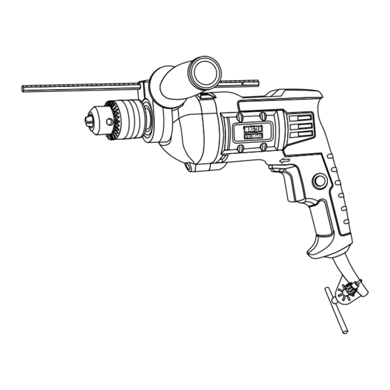
Page 10: Know Your Hammer Drill
KNOW YOUR HAMMER DRILL Depth stop rod Drill/hammer mode switch Chuck Air vents Auxiliary Lock-on handle button Forward/reverse switch Chuck Variable speed trigger switch ACCESSORIES AVAILABLE ACCESSORIES Before using any accessory, carefully read the instructions or the owner’s manual for WARNING: Use only accessories the accessory. -
Page 11: Contents
CONTENTS CONTENTS HAMMER DRILL COMPONENTS DESCRIPTION Carefully unpack the drill. Compare the Drill contents against the “HAMMER DRILL Chuck key COMPONENTS” chart at right. Depth rod Auxiliary handle NOTE: See illustration of the drill below. Owner’s Manual WARNING: To avoid fire or toxic reaction, never use gasoline, naphtha, acetone, lacquer thinner or similar highly volatile solvents to clean the... -
Page 12: Assembly And Operating
ASSEMBLY AND OPERATING FORWARD/REVERSE SWITCH The forward/reverse switch (1) is conveniently mounted in front of the trigger switch (2) (Fig. 1). To make the drill rotate clockwise for drilling, push the forward/reverse switch to the left. To make the drill rotate counter-clockwise, push the forward/reverse switch to the right. -
Page 13: Drill / Impact Switch
ASSEMBLY AND OPERATING DRILL / IMPACT SWITCH The drill / impact switch (1) changes the drilling mode between conventional drilling and impact for drilling concrete. To operate the drill in drill mode, push the drill / impact switch to the right (Fig 3A). To operate the drill in impact mode, push the drill / impact switch to the left (Fig. -
Page 14: Installing Drill Bits
ASSEMBLY AND OPERATING INSTALLING DRILL BITS WARNING: Never hold the chuck body with one hand and use the drill power to rotate the drill body to loosen or tighten bits. Serious injury may result. Remove drill plug from the power source. -
Page 15: Removing Drill Bits
ASSEMBLY AND OPERATING WARNING: Do not insert the drill bit into the chuck and tighten as shown in Fig. 5. The drill bit MUST be properly inserted with all three of the chuck jaws holding the bit centered in the chuck. Failure to properly insert the drill bit could cause the drill bit to be thrown from the chuck, resulting in possible... -
Page 16: Installing The Auxiliary Handle
ASSEMBLY AND OPERATING INSTALLING THE AUXILIARY HANDLE Install the auxiliary handle (1) for two handed operation of the drill (Fig. 7). This is particularly important for drilling in concrete. Rotate the auxiliary handle counter clockwise to open mounting collar (2). Slide the auxiliary handle collar over the chuck and fully onto the drill housing (3). - Page 17 ASSEMBLY AND OPERATING WARNING For safety reasons, the operator must read the sections of this Owner’s Manual entitled "GENERAL SAFETY WARNINGS", "POWER TOOL SAFETY", "SPECIFIC SAFETY RULES", "EXTENSION CORD SAFETY" and "SYMBOLS" before using this drill. Verify the following every time the drill is used: Safety glasses, safety goggles, or face shield is being worn.
-
Page 18: Drilling
ASSEMBLY AND OPERATING DRILLING When drilling into smooth, hard surfaces such as metal, use a center punch to mark the desired hole location. This will prevent the drill bit from slipping off center as the hole is started. The workpiece to be drilled should be secured in a vice or with clamps to keep it from turning as the drill bit rotates (Fig. - Page 19 ASSEMBLY AND OPERATING DRILLING – cont’d Move the drill bit into the workpiece applying only enough pressure to keep the bit cutting. Do not force the drill bit or apply sideways pressure to elongate the hole. WARNING: Be prepared for binding and bit breakthrough.
-
Page 20: Removing The Chuck
ASSEMBLY AND OPERATING REMOVING THE CHUCK To remove the chuck: Remove the drill plug from the power source. Insert a 5/16” (8 mm) or larger hex key (1) into the chuck (2) and tighten the chuck jaws securely (Fig. 10). Make sure each of the chuck jaws (3) is seated on the flat surfaces of the hex key. -
Page 21: Retightening A Loose Chuck
ASSEMBLY AND OPERATING RETIGHTENING A LOOSE CHUCK After installing a chuck that has previously been removed, the chuck may become loose on the spindle and develop a wobble. Also, the chuck screw may become loose, causing the chuck jaws to bind and prevent them from closing. -
Page 22: Maintenance
MAINTENANCE GENERAL WARNING: When servicing, use only identical replacement parts. The use of any other part may create a hazard or cause product damage. DO NOT use solvents when cleaning plastic parts. Plastics are susceptible to damage from various types of commercial solvents and may be damaged by their use. -
Page 23: Exploded View
EXPLODED VIEW... -
Page 24: Parts List
PARTS LIST WARNING: When servicing, use only original equipment replacement parts. The use of any other parts may create a safety hazard or cause damage to the hammer drill. Any attempt to repair or replace electrical parts on this hammer drill may create a safety hazard unless repairs are performed by a qualified technician. - Page 25 PARTS LIST Key # Part # Part Name Quantity 2010100025 Impact plate II 2010100024 Impact plate I 4010040001 Copper sleeve 3150150021 Brush holder support 2030070041 Brush holder 1230010096 Carbon brush 2020150060 Middle cover 4010010050 Bearing 609Z 3140090015 Buffer 1020010005 Stator 3011020004 Housing 1010010006...
-
Page 26: Warranty
3-Year Limited Warranty: This product is warranted for 3 years against any defects in material and workmanship. If defective the product will be repaired or replaced free of charge. Simply provide proof of purchase and return the tool to your place of purchase.
Need help?
Do you have a question about the 134468 and is the answer not in the manual?
Questions and answers