
Summary of Contents for Vingtor Stentofon VSS-V2
- Page 1 Installation & User Manual SOUND RECEPTION SYSTEM VSS-V2 TECHNICAL MANUAL A100K11209 v1.4...
- Page 2 About this Document Document Scope This document describes system features, models, interfaces and functions for the VSS-V2 Sound Reception System. It also includes instructions for installation, commissioning and adjustment, and provides the end-user with the necessary information to operate the VSS-V2 system.
-
Page 3: Table Of Contents
Audio Interface ................10 4 Installation & Configuration Procedures ........11 General ................... 11 Mounting ................. 11 4.2.1 VSS-V2 Master Panel & VSS-V2 Slave Panel ....11 4.2.2 VSS-V2 Microphone Unit ..........11 4.2.3 Microphone Cable Precautions........12 4.2.4 Compass safety distance ..........12 Terminals, Jumper and Potentiometer Configurations ....13 4.3.1 VSS-V2 Master Panel PCB ETC 600-868 .......13... - Page 4 10.6 No detection ................27 10.7 Direction indication wrong ............28 11 Maintenance ...................29 11.1 General ...................29 11.2 Spare Parts ................29 12 Technical Data ................30 12.1 VSS-V2 Master Panel .............30 12.2 VSS-V2 Slave Panel ...............30 12.3 VSS-V2 Microphone Unit ............30 A100K11209 v.1.4 VSS-V2 Technical Manual...
-
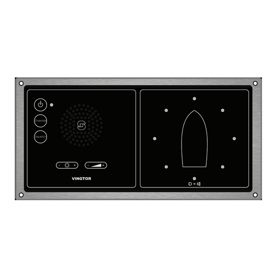
Page 5: Functional Overview
VSS bridge panel. By use of the microphone unit, the VSS-V2 system will detect the direction of the incoming horn signal and activate the corresponding LED at the VSS-V2 front panel. Depending on the signal measured at two adjacent microphones, additional directions between those microphones can be measured. -
Page 6: System Drawing
It is possible to connect up to four slave panels to the master panel. Slave panels will, from the operator’s point of view, operate as master panel with access to the same keys and functionalities. A100K11209 v.1.4 VSS-V2 Technical Manual... -
Page 7: Models
1.5 Models 1.5.1 VSS-V2 Master Panel Dimensions (W x H x D): 280 x 140 x 120 mm 1.5.2 VSS-V2 Slave Panel Dimensions (W x H x D): 280 x 140 x 53 mm A100K11209 v.1.4 VSS-V2 Technical Manual... -
Page 8: Vss-V2 Microphone Unit
1.5.3 VSS-V2 Microphone Unit Dimensions (H x W): 660 x 250 mm Wind Shield Microphone Unit Amplifier and Connection box Support/Fastening plate 1.6 Target Groups According to requirements, this product is mandatory on all ships with enclosed bridges. A100K11209 v.1.4 VSS-V2 Technical Manual... -
Page 9: Interfaces
6-wire interface to slave panel consists of power lines, balanced audio signal and RS485 communication lines. 2.3 Microphone Unit 10-wire interface to microphone consists of power lines and 2-wire set for each microphone. Microphone lines have balanced audio signal and its own keep-alive signal. A100K11209 v.1.4 VSS-V2 Technical Manual... -
Page 10: Functions
3.3 Mute Input Public Address This mute input will disconnect the VSS microphones when public address messages are broadcasted. 3.4 Audio Interface This is an external audio interface. It is possible to adjust audio volume by a potentiometer. A100K11209 v.1.4 VSS-V2 Technical Manual... -
Page 11: Installation & Configuration Procedures
Installation & Configuration Procedures 4.1 General For proper installation and operation of the VSS-V2 system, we recommend reading this section thoroughly together with technical and connection drawings. L Zenitel has experienced that certain types of ships have a too high ambient noise level in the area where the microphone unit is installed. -
Page 12: Microphone Cable Precautions
This is necessary to reduce ship-borne vibrations reaching the sensitive microphone elements. 4.2.4 Compass safety distance All units must be mounted with a distance of 70 cm from the vessel’s standard compass and steering compass. A100K11209 v.1.4 VSS-V2 Technical Manual... -
Page 13: Terminals, Jumper And Potentiometer Configurations
• Terminal Block K3 Switch for muting Typhoon/foghorn • Terminal Block K4 Audio out to Voyage Data Recorder (VDR) • Terminal Block K5 - K8 VSS-V2 Slave Panels • Terminal Block K9 24V Power supply • DIP switch S1/4 Background Light On/Off DIP switch S1/2: Reverse LED function •... -
Page 14: Vss-V2 Microphone Amplifier Pcb Etc 600-870
4.3.3 VSS-V2 Microphone Amplifier PCB ETC 600-870 • Terminal Block K1 Connection to VSS-V2 Master panel 4.4 Cable Requirements All signal cables have to be approved ship cable of type twisted-pair with outer braided copper shield. See section 4.7 Cable Connection Diagram for further details. -
Page 15: Cable Connection Diagram
4.7 Cable Connection Diagram A100K11209 v.1.4 VSS-V2 Technical Manual... -
Page 16: Dimensions & Mounting Details
Dimensions & Mounting Details 5.1 VSS-V2 Microphone Unit ● Dimensions in mm A100K11209 v.1.4 VSS-V2 Technical Manual... -
Page 17: Vss-V2 Master Panel
5.2 VSS-V2 Master Panel ● Dimensions in mm A100K11209 v.1.4 VSS-V2 Technical Manual... -
Page 18: Vss-V2 Slave Panel
5.3 VSS-V2 Slave Panel ● Dimensions in mm A100K11209 v.1.4 VSS-V2 Technical Manual... -
Page 19: Startup And Commissioning Of System
Startup and Commissioning of System 6.1 General The VSS-V2 units have been fully tested in our test laboratory before delivery. To ensure that the system operates properly after installation and configuration, carry out the following procedures before using the system. -
Page 20: Installation Performance Test
For the VSS-V2 resolution of direction detection is eight (8). The system is tested according to ISO 14859:2012 . For a performance test at installation site as the following test procedure is recommended. -
Page 21: Check The Following
7.3 Check the following 1. Sound signal is being presented in speaker 2. Visual check that direction indication is correct 3. Visual check that direction indication is the duration of the detected horn signal plus two (2) seconds. A100K11209 v.1.4 VSS-V2 Technical Manual... -
Page 22: Operation Instructions
The volume level has eight steps indicating from 1 to 8 LEDs lit, 8 being maximum volume and 1 the minimum. This can be shown by pressing the volume buttons. When powering on the system or making an off/on cycle, the volume will be set at default level. A100K11209 v.1.4 VSS-V2 Technical Manual... -
Page 23: Squelch
15s. 8.1.7 Power The power button is for powering the panel on or off. Indication for power ON is via the green LED. 8.2 Web Interface 8.2.1 Open site ● Microphone status and LED direction. A100K11209 v.1.4 VSS-V2 Technical Manual... -
Page 24: Administrator Site
● When setting the IP configuration, default address is 169.254.1.10 which is the address of the VSS web interface page. This can be changed to conform to the existing network. ● ● ● ● ● ● ● ● ● ● ● ● A100K11209 v.1.4 VSS-V2 Technical Manual... -
Page 25: Reverse Led Function
Panel is set in reverse mode by activation of PCB dip-switch. An incoming sound signal is registered at starboard side at the microphone unit. The panel will make its LED indication at opposite direction - in this example it will lid port side. A100K11209 v.1.4 VSS-V2 Technical Manual... -
Page 26: Variant 1 Normal Default Setting
9.3.3 Variant 3 Reverse Reverse verse function mode. Vessel sticker added. LED indication reversed and panel vessel display reversed. The third variant will require an additional item 1021001011 Rev.1.00 VSS-VESSEL Front panel vessel label – V A100K11209 v.1.4 VSS-V2 Technical Manual... -
Page 27: Troubleshooting
This includes filters suppressing background noise from wind, wires and own ships machinery letting only sounds having characteristics reckoned to be a ships whistle pass through. A100K11209 v.1.4 VSS-V2 Technical Manual... -
Page 28: Direction Indication Wrong
LED indication must be finished before new direction is to be tested. Confirm VSS-MP displays corresponding visual LED indication. If this is confirmed panel and microphone operates correctly and malfunction has to be found in placement and surroundings. A100K11209 v.1.4 VSS-V2 Technical Manual... -
Page 29: Maintenance
The housing is regarded as one spare part. It is designed to be easily changeable. Ref. Assembly manual for replacement of microphones A100K11577 VSS-V2 Microphone Replacement v.1 For microphone unit VSS-MU 2.06 & former Ref. Assembly manual for replacement of microphones A100K11577 VSS-V2 Microphone Replacement v.2... -
Page 30: Technical Data
12 Technical Data 12.1 VSS-V2 Master Panel Dimensions (WxHxD 280 x 140 x 90 mm Mounting Flush Housing Brushed aluminum with foil IP rating IP-22 Operation voltage 24V DC Audio 70 Hz to 2’100 Hz Active noise cancellation Adjustable volume... - Page 31 A100K11209 v.1.4 VSS-V2 Technical Manual...
- Page 32 www.zenitel.com Zenitel Norway AS The WEEE Directive does not legislate that Zenitel, as a ‘producer’, shall collect ‘end of life’ WEEE. This ‘end of life’ WEEE should be recycled appropriately by the owner who should use proper treatment and recycling measures. It should not be disposed to landfi ll. Many electrical items that we throw away can be repaired or recycled.
Need help?
Do you have a question about the VSS-V2 and is the answer not in the manual?
Questions and answers