Table of Contents
Advertisement
Advertisement
Table of Contents

Summary of Contents for Richpeace RF-MJ135
- Page 1 Magic Ink-jet Plotter User’s Manual 富怡集团. 天津宝盈电脑机械有限公司 Richpeace Group Co., Limited Tianjin Richpeace Computer & Machinery Co., LTD. 天津工厂地址:天津市宝坻经济开发区宝中道 6 号(301800) Factory Address: No.6 Baozhong Road, Baodi Economic Development Zone, Tianjin City China. 公司网址(Website): www.richpeace.com...
-
Page 2: Table Of Contents
Content Make sure to operate safely and accurately ..................I Safe Notice I ............................ II Safe Notice II ..........................IV Chapter1 Install Plotter ........................1 1.1 Check accessory ........................2 1.2 Technical parameter ........................4 1.3 Structure and installation of new model plotter ................. 5 1.3.1 Structure and parts functions .................. -
Page 3: Make Sure To Operate Safely And Accurately
Make sure to operate safely and accurately In order to operating the plotter safely and accurately, please read the manual carefully before using the plotter. In order to reading it quickly when you needed, please put it at the place where you can get it conveniently after reading carefully. -
Page 4: Safe Notice I
Continuing to use the plotter under these situations might cause fire or electrical attack. Make sure the plotter is not smoking any longer, please contact the salesman or Richpeace authorized agent for maintaining. Forbidden Please don‟t maintain the plotter yourself; it is very danger to maintain by unfamiliar person. - Page 5 Don‟t let the dust and the metal material adhibit to the power plug. The dirty power plug might cause electrical attack or fire Forbidden by creepage. Take Care Electrical Attack Please don‟t touch the print head and the moving parts when plotting. These actions might cause body injured.
-
Page 6: Safe Notice Ii
If there are water or eyewinker in the machine, please stop using it. Turn off power and pull out the power cable from the electrical outlet. Using the plotter under these situations might cause electrical attack or fire by creepage. Pull power Contact the salesman or Richpeace authorized agent to maintain it. cable from electrical outlet. - Page 7 Don‟t pull it forcibly when you need to pull out the power wire or Cable. These actions might damage electrical wire and cause fire or electrical attack. Forbidden Don‟t try to append lube for the plotter. These actions might cause mechanical malfunction. Forbidden Don‟t use the thinner or gas to clear machine.
-
Page 8: Chapter1 Install Plotter
Chapter1 Install Plotter 1.1 Check the accessory 1.2 Technical parameter 1.3 Structure and installation of new model plotter 1.4 Structure and installation 1.5 Structure and installation of MJ 135 plotter 1.6 Connect to computer... -
Page 9: Check Accessory
1.1 Check accessory Refer to the standard accessory list as follows, check and make sure there is not missing . If there has missing accessory, please contact the salesman or Richforever authorized local agent. Power cable one piece USB data cable one piece Bolt M6*40,flat&spring washer 4 sets Allen key M3, M5 one set Ink box two pieces(four pieces for four heads) Manual book 1... - Page 10 Whole machine includes parts as follows: Plotter head one set Left & right stand each one set Beam one set Roll shaft and feed shaft each one set Balance paper bar two pieces ( MJ135 with one Paper hold one set two pieces piece)...
-
Page 11: Technical Parameter
1.2 Technical parameter Plotter technical parameter: Type RF-MJ135 RF-MJ180 RF-MJ200 RF-MJ220 RF-MJ300 Function Max paper width 140cm 185cm 205cm 225cm 305cm Max plotting width 138cm 183cm 203cm 223cm 303cm Max cartridges 2 or 4 Receiving paper None Automatic paper receiving... -
Page 12: Structure And Installation Of New Model Plotter
1.3 Structure and installation of new model plotter 1.3.1 Structure and parts functions As following figure shows, compared with common model plotter, the difference is feeding system and receiving system are on same side, save space; low the roll motor near ground, it is more convenient to install paper. -
Page 13: Installation
1.3.2 Installation Stand configuration Bottom stand:left stand、right stand、beam and bar. Paper rod guide Left stand Beam Right stand Balance bar Installation 1. Encase the spring washer and flat washer into the six-angle bolt. (See as follows) Bolt Flat washer Allen key Spring washer 4 sets 2. - Page 14 hole Screw hole There are two holes at the stands and both sides of the beam. Operation 4. After finishing the installation of the left and right stands, install the plotter head on the stand. Lift up the head, put it on the stand, plug the head angle iron notch on the stand bolts, fasten the butterfly screws after putting away the both sides of the head, and then fix the head on the stand.
- Page 15 5. Connection Plug the roll and feed motor cable at the left side into the aviation sockets. (Fig1) Aviation socket Motor Plug the motor cables at the left stand into the aviation sockets on the left side of the plotter head. Figure 1 Plug the sensor cable at the right side into the aviation socket of the plotter.
-
Page 16: Install Paper
1.3.3 Install paper 1.Plunge paper feed shaft through The dimension of installing the plotter paper roll, then fix the paper as picture, please don’t make the dimension paper by fastening hubs on both oppositely. sides of paper feed shaft Paper shaft Feed shaft . - Page 17 Feed shaft Feed shaft seat Figure 1 Feed motor driver Feed shaft Feed motor driver Feed shaft seat Figure 2 Caution The max weight of paper roll is 35kg; it would damage motor if the paper roll is too heavy. 5.
- Page 18 Pull the paper to the front side of the plotter through the plotter head 6. After pulling out the paper, please make the paper roll stillness, pull the paper evenly, make sure the pulling strength is the same on the both sides of paper and then stick the paper on the receive shaft from middle to both sides.
- Page 19 Spanner Running pole Lift up spanner; press the pressure wheels to control the paper movement. 9. Please put the balance paper bars on paper and plug them into the balance paper bar slots on both sides. (See as follows) Bar slot Balance bar 10.
-
Page 20: Paper Cutting
1.3.4 Paper cutting Step one Step two Step three: Press the number key adjust the best printing paper height 1.4 Structure and installation At present, our company produces three kinds of plotters with different structure: common model (roll shaft and feed shaft are on different sides)、 MJ135(without receiving system)、 new model (roll shaft and feed shaft are on same side). -
Page 21: Structure And Parts Functions Of Common Model
1.4.1 Structure and parts functions of common model Face Print head Pressure wheel device Left cover Roll Control panel motor Right cover Receive shaft seat Left stand Roll shaft Right stand Bar slot Stand foot Pressure wheel device Main part of the device Axes Pressure wheel Grinding wheel On the plotter, the paper movement of plotter is between pressure wheels and grinding wheels. - Page 22 Note Please move the pressure wheels to proper site according to the plotter paper, and put them on the grinding wheels; otherwise it cannot plot normally or lacerate paper. Please lift up the pressure wheels when the plotter does not work to prolong the life of the plotter. ...
- Page 23 Back Power switch Power outlet Com switch LAN cable port USB port PPPower outlet: Connect power to the plotter LAN cable port: Used to connect LAN cable Power switch: used to turn on/off the plotter USB port: Used to connect USB cable Control panel Function: Use to modify the setting function in 、...
-
Page 24: Installation
1.4.2 Installation Stand configuration Bottom stand: left stand, right stand and beam. Right stand Left stand Installation 1. Encase the spring washer and flat washer into the six-angle bolt. (See as follows) Bolt Flat washer Allen key Spring washer 4 set 2. - Page 25 hole Screw hole There are two holes at the stands and both sides of the beam. Operation 4. After finishing the installation of the left and right stands, install the plotter head on the stand. Lift up the head, put it on the stand, plug the head angle iron notch on the stand bolts, fasten the butterfly screws after putting away the both sides of the head, and then fix the head on the stand.
- Page 26 5.Connection Plug the roll and feed motor cable at the left side into the aviation sockets. Aviation socket Plug the motor cables at the left stand into aviation sockets on the left side of the plotter head Motor cable Fig 1 Plug the sensor cable at the right side into the aviation socket of the plotter.
-
Page 27: Install Paper
1.4.3 Install paper 1. Plunge paper feed shaft through the plotter paper roll, then fix the The dimension of installing paper by fastening hubs on both sides paper as picture, of paper feed shaft. please don‟t make the dimension Feed shaft oppositely. - Page 28 3. Fasten screws with Allen key; make sure the shaft and the paper roll have no opposite movement. 。 Allen key Fasten screw 4. Lift up the feed shaft with paper roll, then put the left side of feed shaft into the left feed shaft seat (please following fig1), then put the right side of paper feed shaft into the feed shaft seat, please let the motor driver completely plunge into the right side of the Feed Shaft.
- Page 29 Feed motor driver Feed shaft Feed motor driver Feed shaft seat 图二 Caution The max weight of paper roll is 35kg; it would damage motor if the paper roll is too heavy. 5. Please put the paper under pressure wheels, and put the paper through the plotter head after paper roll is installed on plotter correctly (please note to lift up the pressure wheels), then pull paper to the front of the plotter.
- Page 30 6. After pulling out the paper, please make the paper roll stillness, pull the paper evenly, make sure the pulling strength is the same on the both sides of paper and then stick the paper on the receive shaft from middle to both sides.
- Page 31 Spanner Running pole Lift up spanner; press the pressure wheels to control the paper movement. 9. Please put the balance paper bars on paper and plug them into the balance paper bar slots on both sides. (See as follows) Balance paper bar Bar slot 10.Please rotate feed shaft and roll shaft to make balance paper bars between top and bottom sensors.
-
Page 32: Install Ink Box
Receiving bar Sensor Bar slot Balance bar 1.4.4 Install ink box MJ inkjet plotter uses the model 51645Aink box; it can be bought at every Hp franchise, please use quality goods for good print quality. Step one Step two... -
Page 33: Structure And Installation Of Mj135 Plotter
Step three Please install the ink box vertically into the print head, push the ink box to the bottom and the spanner of the print head. You can check the left ink by looking the small window of the ink box, if there shows black that means no ink, you should change the ink box immediately, if there shows green, that means the ink is full. -
Page 34: Installation
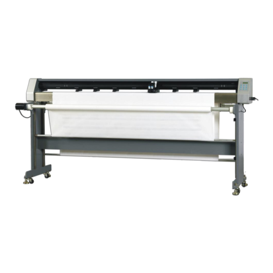
Square bar Table 1-2 Cloth Collect paper plotted Butterfly screw Fasten support to stand Support Support square bar Square bar Support cloth Functions of other parts please check table 1-1. 1.5.2 Installation The installations of stand、head、ink box and paper for MJ 135plotter are as same as common model plotters, here we wouldn‟t repeat. -
Page 35: Connect To Computer
support Butterfly screw 2. Put two square bars through the two sides of cloth, put one piece of bar in notch that on the support, and put another bar in the bar seat behind the beam. Bar seat 1.6 Connect to computer 1. - Page 36 1 white-orange 1 white-orange 2 orange 2 orange 3 white-green 3 white-green 4 blue 4 blue 5 white-blue 5 white-blue 6 green 6 green 7 white-brown 7 white-brown 8 brown 8 brown RJ45 Modular Plugs RJ45 Modular Plugs If the plotter connects to the computer, the cable should be cross-cover, made as follows: One side: white-orange/orange/white-green/blue/white-blue/green/white-brown/brown The other side: white-green /green/ white-orange /blue/white-blue/orange/white-brown/brown 3 white-green...
-
Page 37: Chapter2 Basic Setting And Operation
Chapter2 Basic setting and operation 2.1 Origin setting 2.2 Plot test graph 2.3 Delete file 2.4 Sensor check 2.5 Keyboard check 2.6 Collection start and stop 2.7Print head cleaning times 2.8Version info... -
Page 38: Origin Setting
2.1 Origin setting Origin is the start point when printing. Before printing, set the position of the origin up to the paper position. You must make sure the marker is totally inside the paper when setting the origin. LCD displays: Operation process: Turn on plotter, and it shows welcome to use System initialing... -
Page 39: Plot Test Graph
2.2 Plot test graph The function is for testing whether the ink box is jammed, so we can make sure whether need to change or clean the ink box. LCD displays: Operation process: System initialing 1. Turn on plotter, and it shows welcome to use Please waiting! enrich plotter. -
Page 40: Delete File
2.3 Delete file The function is for deleting the file that has been sent to the plotter by mistake. LCD displays: Operation process: 1. Turn on plotter, and it shows welcome to use System initialing Please waiting! enrich plotter. 2. Press „7‟ to pause the plotter. LCD displays to Initializing successfully enter into the origin setting function. -
Page 41: Sensor Check
2.4 Sensor check The function is used to check whether all the sensors are working, when one sensor is blocked, the screen will show the name of the sensor, and only one sensor can be checked at one time, if the sensor is damaged, the screen shows nothing. -
Page 42: Keyboard Check
2.5 Keyboard check The function is for checking every key‟s correctness; you must check all the nine keys. LCD displays: Operation process: System initialing 1. Turn on plotter, and it shows welcome to use Please waiting! enrich plotter. 2. Press „7‟ to pause the plotter. LCD displays to Initialing successfully enter into the origin setting function. -
Page 43: Collection Start And Stop
2.6 Collection start and stop This function is mainly to control motor collect paper and back paper. LCD displays: Operation process: System initialing 1. Turn on plotter, and it shows welcome to use Please waiting! enrich plotter. 2. Press „7‟ to pause the plotter. LCD displays to Initialing successfully enter into the origin setting function. -
Page 44: Print Head Cleaning Times
2.7 Print head cleaning times The function used before the settings file printed,print head cleaning times,setting range”1`5” LCD displays: Operation process: 1.Turn on plotter, and it shows welcome to System initialing Please waiting! use enrich plotter. 2.Press „7‟ to pause the plotter. LCD displays Initialing successfully to enter into the origin setting function. -
Page 45: Version Info
2.8Version Info The function only shows the version number and the data, it can„t be modified. LCD displays: Operation process: System initialing 1. Turn on plotter, and it shows welcome to use Please waiting! enrich plotter. 2. Press „7‟ to pause the plotter. LCD displays to Initialing successfully enter into the origin setting function. -
Page 46: Chapter3 Plot
Chapter3 Plot 3.1 Plotcenter 3.2 File 3.3 Tools 3.4 Language 3.5 Setup 3.6 Calibration 3.7 Plot sequence 3.8 Print preview 3.9Operations after plotting... -
Page 47: Plotcenter
3.1 Plotcenter The plotcenter is only used for Richpeace plotter, the figure of the plotcenter as follows: Please modify the calibration of the plotter when installing the machine and make sure the output measures are no problem. It can be modified in the plotcenter to modify the calibration of the HPGL file, please refer to „3.6 Calibration‟. - Page 48 3. Open Open the HPGL file you want to plot. Operation process as follows: (1)Click the „open‟ menu in the plot menu: (2)Popup „open‟ dialogue, choose the needed files:...
- Page 49 (3). Click „open‟, popup a window as follows: Start point: you can input the value then plotter will start plotting from the value position. Copies: input the value to set the plotting times. Plot: click plot to start plotting. For example the plotting is suddenly stopped because of the plotter power is off, then we don‟t need to plot the total marker again, only need to click „exit‟...
- Page 50 4. Test It can plot out a test graph. 5. Pause It can stop sending data which is in the plotting sequence. Choose the file which needs pause,then click pause. After pause,the file will change from wait to pause.
- Page 51 6 .Restart Restart plotting the paused files. 7. Delete Delete the files in the sequence, if the file is plotting, the plotter will turn to the main screen. Operation process as follows: (1). Choose „delete‟ menu in the plot menu, delete the file: (2).Click Delete,the following dialogue will appear.
-
Page 52: Tools
8. Exit If there are unfinished files, it will indicate as follows: 3.3 Tools 1. Input parameter Input the mainboard parameter from the file PlotPara.ini in the plotcenter folder. 2. Output parameter Output the mainboard parameter to the file PlotPara.ini in the plotcenter folder. - Page 53 3. AutoPlotDir 1. Click AutoPlotDir Set the folder are already shared, then click OK, now the other computers can send the plotting files to the plotcenter to achieve the network plotting. 4 .History The plotting history of the plotter: Click History to get the following dialog, it will show you all the information that you have plotted out, if the files are still at the origin place, you can click „plot‟...
-
Page 54: Language
3.4 Language We have two Languages for you to choose, English and Simplified Chinese... -
Page 55: Setup
3.5 Setup 1. Communication setting Communication setting in plotcenter means setting of plotter and computer, both of them must have uniform setting, otherwise it is impossible to communicate. There are two communication models, USB and LAN, when it connected, USB and LAN will change to gray color, that means connection is normal and it can start to plot. - Page 56 plotcenter IP, plotter IP, the plotter IP and plotcenter IP are same, the computer IP is different with them, for example: computer IP is 192.168.1.A/255.255.255.0/192.168.1.1, the plotter/plotcenter IP should be 192.168.1.B/255.255.255.0/192.168.1.1, A and B must be different. If all IP set up correct,open plotcenter again ,the number of “set up” menu of each sub menu is new parameter instead of acquiescent.
- Page 57 Plotter IP: LCD displays: Operation process: 1. Turn on plotter, and it shows welcome to use System initialing Please waiting! enrich plotter. 2. Press „7‟ to pause the plotter. LCD displays to Initialing successfully enter into the origin setting function. Press 3.
- Page 58 Plotcenter IP: LAN setting of the plotcenter is the plotter‟s setting, they must be the same, or it can‟t connect to each other. Operation process as follows: 1. Open the „Setup‟ menu in the plotcenter: 2. Choose „Network‟ in the „communications setting‟ menu, interface shows as follows: 3.Modify the parameters of the „Network setup‟...
- Page 59 2. Plot setting: 1. Click „Setup‟in the plotcneter dialog: 2.Click „Plot setting‟ to get the following dialog: Rotating 90 degree: change the plotting direction Use Vector font: use to make the font width same as the original Setup line width: set the plotting line width Paper width: set the maximum plotting width, if the marker width is wider than the paper width, the marker will be split to several parts and plot out.
- Page 60 2. Click „Plotter setting‟to get the following dialog. Select print style: it is for modifying the style, includes unidirectional and bidirectional. Unidirectional is only plotting from the right side to the left side, not plotting when return to the right side. Bidirectional is plotting from left side to the right side and right side to the left side.
-
Page 61: Calibration
3.6 Calibration Operation as follows: 1. Plot out a 1meter rectangle and measure the length and width. 2. Choose the „plotter setup‟ under the „setup‟ menu and popup the „plotter setup‟ window. 3.Input the actual length and width that you have measured to „plotter error correct‟ dialog. Now the calibration is modified. -
Page 62: Plot Sequence
3.7 Plot sequence When you plot several files continuously, you can change the plot order by clicking the „Forward‟, „Backward‟, „Head‟, „Tail‟ icons. Operations as follows: 1. For example, there are four files in the plotcenter, 1.plt, 2.plt, 3.plt, and 4plt. 2. -
Page 63: Operation After Plotting
3.Press draw or close will bow out print preview menu. 3.9 Operation after plotting If you need plot other file when one marker is finished, you can also send the other file without close the plotcenter. If you want to finish plotting, you can take out the balance bar and cut off the paper, the cutting position as follows: Cutting slot Caution... -
Page 64: Chapter4 Trouble Shooting
Chapter4 trouble shooting 4.1 Error indication 4.2 Note... -
Page 65: Error Indication
4.1 Error indication The plotter can indicate the error on the LCD screen automatically if problem occurred, so it will help the operator to find solutions. Error indication and malfunction reason as follows: 1、 Paper out Reason: When feeding paper or plotting, the „feed paper start‟ sensor works. Solution: Reinstall the paper and press „7‟;...
Need help?
Do you have a question about the RF-MJ135 and is the answer not in the manual?
Questions and answers