Table of Contents
Advertisement
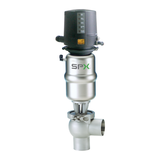
APV DELTA SW4
S I N G L E S E AT A N D C H A N G E - O V E R VA LV E
F O R M N O . : H 1 7 0 7 3 3
R E V I S I O N : U K - 4
Scan for SW4 Valve
Maintenance Video
R E A D A N D U N D E R S TA N D T H I S M A N U A L P R I O R TO O P E R AT I N G O R S E RV I C I N G T H I S P R O D U C T.
I N S T R U C T I O N M A N U A L
Advertisement
Table of Contents

Summary of Contents for SPX FLOW APV DELTA SW4
- Page 1 I N S T R U C T I O N M A N U A L APV DELTA SW4 S I N G L E S E AT A N D C H A N G E - O V E R VA LV E F O R M N O .
- Page 3 Directives 2006/42/EC (superseding 89/392/EEC and 98/37/EC) and ProdSG (superseding GPSG - 9.GPSGV). For official inspections, SPX FLOW presents a technical documentation according to Appendix VII of the Machinery Directive, this documentation consisting of documents of the development and construction, description of measures taken to meet the conformity and to correspond with the basic requirements on safety and health, incl.
-
Page 5: Table Of Contents
APV_SW4_UK-4_082017.indd Table of Contents Page General Terms Safety Instructions 2 - 3 Intended Use Mode of Operation 4.1. General terms Auxiliary Equipment 5 - 6 5.1. Valve position indicator 5.2. Control unit 5.3. Stroke limitation SW4 / M4 5.4. Oil dampening cylinder 5.5. -
Page 7: General Terms
The valve must only be assembled, operated, disassembled, serviced and repaired by persons who have been trained accordingly. Please contact your local SPX FLOW representative if necessary. Danger! This technical safety symbol draws your attention to important directions for operating safety. You will find it wherever the activities described are bearing health hazards or risks for persons or material assets. -
Page 8: Safety Instructions
Opening of the actuators is strictly forbidden. Danger to life! Actuators which are no longer used or defective must be disposed in professional manner. Defective actuators must be returned to your SPX FLOW representative for their professional disposal and free of charge for you. Intended Use The intended use as field of application of the DELTA SW4 single seat and change-over valves is the shut-off of line sections. -
Page 9: Mode Of Operation
APV_SW4_UK-4_082017.indd Mode of Operation 4.1. General terms Single seat valve Single seat and change-over valves DELTA SW4 have been developed for use in the brewing and beverage, dairy and food control unit industries as well as for chemical and pharmaceutical applications. actuator screw The valves are designed for universal applications and stand out for their increased mechanical reliability and absolute ease of... -
Page 10: Auxiliary Equipment
APV_SW4_UK-4_082017.indd Auxiliary Equipment 5.1. Valve position indication (fig. 5.1.) Proximity swith holders (PSH) for the valve position indication can fig. 5.1. be mounted direct on the actuator. Proximity switches to signal the limit position of the valve seat can be installed at the proximity switch holder. -
Page 11: Stroke Limitation Sw4 / M4
APV_SW4_UK-4_082017.indd Auxiliary Equipment 5.3. Stroke limitation SW4 / M4 (fig. 5.3.) The pneumatic stroke limitation provides for the continuous fig. 5.3. adjustment of the total valve stroke of 0 - 100%. The pneumatic stroke limitation is installed on the actuator. The valve disc can be in the three different positions: open, throttled and closed. -
Page 12: Cleaning
APV_SW4_UK-4_082017.indd Cleaning 6.1. Cleaning recommendation Flow passages The passages of the valve are cleaned by the cleaning liquid during cleaning of the connected pipelines. Depending on the degree and substances of soiling, cleaning liquids, times and processes must be scheduled for the individual application. -
Page 13: Welding Instructions
APV_SW4_UK-4_082017.indd Installation 7.3. Welding Instructions Shut-off valve Before welding of the valve, the valve insert must be dismantled from the housing. Careful handling to avoid damage to the parts is necessary. Change-over valve: Before welding of the valves, the valve insert must be dismantled from the housing. -
Page 14: Dimensions / Weights
APV_SW4_UK-4_082017.indd Dimenions/Weights 8.1. Single seat valve Single seat valve Valve position indicator with CU4 control unit housing variants Ø 134 SW 41 SW 42 SWE 43/44 SWE 43 Ø K SWE 44 SWE 41/42 Dimensions in mm Weight in kg ∅... -
Page 15: Dimensions/Weights
APV_SW4_UK-4_082017.indd Dimensions/Weights 8.2. Change-over valve Change-over valve Valve position indicator with CU4 control unit housing variants Ø 134 Ø K SWE 45/46 Dimensions in mm Weight in kg ∅ Di ∅ G ∅ K 47,5 Inch 1" 22,6 16,3 50,6 1,5"... -
Page 16: Technical Data
APV_SW4_UK-4_082017.indd Technical Data 9.1. General data Product-wetted parts: 316 L, 1.4404 (DIN EN 10088) Other parts: 1.4301 (DIN EN 10088) Seals: standard design: EPDM Option: HNBR, VMQ, HNBR Max. line pressure: 10 bar Operating pressure: depending on actuator - see 9.6 Max. -
Page 17: Closing Times
APV_SW4_UK-4_082017.indd Technical Data 9.3. Closing times for single seat and change-over valves The opening and closing times of the valves which are equipped with a control unit, can be fixed through adjustment of the throttling screws at the solenoid valve. Closing times in sec Pneumatic air pressure 6bar hose length 1 m... - Page 18 APV_SW4_UK-4_082017.indd Technical Data 9.6. DELTA SW4 calculatory product pressures in (bar) at 6 bar pneumatic air pressure Single seat valve Single seat valve SW41 NO with SW41 FS 6 bar air pressure Change-over valve Change-over valve Change-over valve Change-over valve SW43 NC SW43 NO with SW43 NC upper seat...
-
Page 19: Technical Data
APV_SW4_UK-4_082017.indd Technical Data 9.7. DELTA SW4 kvs values in m³/h SW41, 42 SW41, 42 SW42 SW43, 44 SW43, 44 SWE41, 42 SWE41, 42 SWE42 SW47, 48 SW47, 48 SWE43, 44 SWE43, 44 SW44 Inch 1" 1,5" 2" 2,5" 3" 4" Single seat and change-over valve DELTA SW4 Instruction manual: UK - rev.4... -
Page 20: Maintenance
APV_SW4_UK-4_082017.indd 10. Maintenance The maintenance intervals depend on the corresponding Scan for SW4 Valve application and are to be determined by the operator himself Maintenance Video carrying out temporary checks. The valve must not be cleaned with products containing abrasive or polishing material. -
Page 21: Service Instructions - Single Seat Valve
APV_SW4_UK-4_082017.indd Service Instructions for Single seat valve Single seat valves Single seat valve DELTA SW41, SW42, SWE41, SWE42, SWE43, SWE44 11.1. Dismantling from line system control unit 1. Shut off line pressure and drain lines if possible. actuator screw hex. nut Valve design NC: Control actuator with air. - Page 22 APV_SW4_UK-4_082017.indd Service Instructions for Single seat valve 11.3. Installation of seals and assembly of valve fig. 11.3.1. 1. Insert the guide bushing into the yoke. Afterwards, insert the shaft seal and press in the slightly greased seat seal (see fig. 11.3.1.). See to the correct installing position.
-
Page 23: Service Instructions - Actuator
APV_SW4_UK-4_082017.indd 12. Service Instructions for Actuator 12.1. Maintenance of actuator fig. 12.1. 1. Remove the air hoses from the actuator. seal screw piston rod v-seal 2. Remove the inner hexagon screws from the adapter of the control unit. o-ring 3. Unscrew the two seal screws with a spanner SW30 while holding up the actuator with a strap wrench. -
Page 24: Service Instructions - Change-Over Valve
APV_SW4_UK-4_082017.indd 13. Service Instructions for Change-over valve 13.1. Dismantling from the line system 1. Shut off line pressure and drain lines if possible. Change-over valve 2. Release connection between the upper housing globe and control unit the connected line. actuator screw 3. - Page 25 APV_SW4_UK-4_082017.indd 13. Service Instructions for Change-over valve 13.3. Installation of seals and assembly of valve 1. Insert the guide bushing into the yoke. Then place the shaft seal fig. 13.3.1. and press in the slightly greased seat seal. See to the correct installing position. 2.
-
Page 26: Assembly Tool
APV_SW4_UK-4_082017.indd Assembly Tool The assembly tool consists of: thrust ring ring with venting nose housing threaded bolt Installation of seat seal in the valve shaft 1. Insert the valve shaft into the housing in such a way that thrust ring the seal groove is in the housing. -
Page 27: Reconstruction Of Actuator
APV_SW4_UK-4_082017.indd 15. Reconstruction of Actuator With SW4 valves, the size of the actuator can be changed. Observe the respective line pressure, see table 9.6, to increase or decrease the actuator sizes (Ø 74 mm, Ø 110 mm, Ø 165 mm). 15.1. -
Page 28: Trouble Shooting
APV_SW4_UK-4_082017.indd 16. Trouble Shooting Failure Remedy Valve closed and pressure in upper housing Replace seat seals. Valve is untight. Check line pressure: Permissible line pressure see chapter 9. Leakage in the area of the clamp Replace housing seals. Leakage at upper shaft in the yoke area Replace shaft seal, seat seal and guide bushing. -
Page 29: Spare Parts Lists
APV_SW4_UK-4_082017.indd Spare Parts Lists The reference numbers of the spare parts for the different valve designs and sizes are included in the attached spare parts drawings with corresponding lists. Please indicate the following data to place an order for spare parts: number of required parts reference number designation... - Page 31 23.03.16 Name: Trytko Trytko Geprüft: Ersatzteilliste: spare parts list SPX FLOW Germany Ventil SW41, SW42, SWE41, SWE42, SWE43, SWE44-FS-CU und VSM Blatt Single seat valve SW41, SW42, SWE41, SWE42, SWE43, SWE44-FS-CU and PSH RN 01.054.805 DN25-100 ; 1-4 Zoll / inch...
- Page 39 Trytko Trytko C.Keil Geprüft: Ersatzteilliste: spare parts list SPX FLOW Germany Umschaltventil SW43, 44, 47, 48, SWE45, 46, 47, 48 -FS-CU und VSM Blatt Change over valve SW43, 44, 47, 48, SWE45, 46, 47, 48 -FS-Cu and PSH RN 01.054.807...
- Page 48 P: (+48) 52 566 76 00 F: (+49) (0) 2301-9186-300 F: (+48) 52 525 99 09 SPX FLOW reserves the right to incorporate the latest design and material changes without notice or obligation. Scan for SW4 Valve Maintenance Video Design features, materials of construction and dimensional data, as described in this manual, are provided for your information only and should not be relied upon unless confirmed in writing.
Need help?
Do you have a question about the APV DELTA SW4 and is the answer not in the manual?
Questions and answers