Table of Contents
Advertisement
Advertisement
Table of Contents

Subscribe to Our Youtube Channel
Summary of Contents for Barber-Colman 7EM
- Page 1 Instruction Manual 1262-IN-009-0-03 Model 7EM February 1998...
-
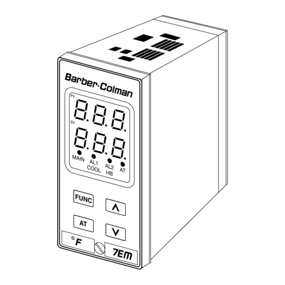
Page 2: Controller
1/8 DIN, THREE DIGIT DISPLAY TEMPERATURE CONTROLLER MODEL: 0 7 E M - 4 3 1 1 0 0 - 0 - 0 0 Field. 1 2 3 4 5 6 7 8 9 10 11 12 13 14 15 Fields 1 through 4. - Page 3 CONGRATULATIONS Unpack the Instrument Congratulations on your purchase of one of the easiest to configure controllers on the market. After a four step configuration procedure, your process will be up and running. Wiring GUIDE TO SIMPLE SET-UP Only four steps are required to set-up your controller: Configuration 1.
-
Page 4: Table Of Contents
Contents CAUTION: 1/8 DIN, THREE DIGIT DISPLAY TEMPERATURE USE WIRE SUITABLE CONTROLLER ..........2 FOR 75 °C MINIMUM MOUNTING REQUIREMENTS ........5 DIMENSIONS AND PANEL CUTOUT ......6 WIRING GUIDELINES ..........7 CONFIGURATION PROCEDURE ......13 Preliminary Hardware Settings ......13 Configuration Key Functions ...... -
Page 5: Mounting Requirements
MOUNTING REQUIREMENTS The instrument can be mounted on a panel up to 15 mm (0.591 in) thick with a cutout of 45 x 92 mm (1.772 x 3.622 in) - see outline in “Dimensions and Panel Cutout.” Select a mounting location with the following characteristics: Panel surface texture must be smoother than 6.3 µm. -
Page 6: Dimensions And Panel Cutout
DIMENSIONS AND PANEL CUTOUT 45 mm, -0, +0.6 mm 1.772 in, -0, +0.024 in 92 mm, -0, +0.8 mm 3.622 in, -0, +0.031 in 125 mm 96 mm 60 mm 4.921 in 3.780 in 2.362 in 48 mm 89 mm 1.890 in 3.504 in 10 mm... -
Page 7: Wiring Guidelines
WIRING GUIDELINES NOTE: Control outputs 1 and 2 are protected by v aristor against an inductive load up to 0.5 Amps. All other outputs, or external contacts in series Terminal board with the instrument outputs, need an external snubber network (RC) across the terminals: PWR LINE 100/240Vac 24 Vac/Vdc... - Page 8 A.1) Measuring inputs RTD input Any external components (like zener diodes, etc.) connected between the sensor and input terminals may cause measurement errors (excessive or unbalanced line resistance or possible leakage currents). TC input SAFETY NOTE: Shield 1) Do not run RTD wires with power cables. NOTES: 1) Ground shielded cable at one end only.
- Page 9 Thermocouple compensating cable color codes. s i t l a i o l l o l l o l l o l l o l l o l l o l l l o i l o i / l i l i s...
- Page 10 A.2) Current transformer input SAFETY NOTE: 1) Do not run current transformer input wiring with AC OUT 2 power cables. (AL1/cooling) NOTE: 1) The minimum active period to perform this measurement is 50 ms. 2) The input impedance is 10 Ω. 3) The maximum input current is 50 mA.
- Page 11 B.3) Voltage outputs for SSR drive B.2) Inductive loads High voltage transients can occur when switching These are time proportioning outputs. inductive loads. It is recommended to install an additional RC network across the internal contacts as shown. Logic voltage for SSR drive. Logic status 1: 24 Vdc ±20% @ 1 mA.
- Page 12 Power line wiring Power Supply 100 to 240 Vac rms (50/60 Hz) or 24 Vac/Vdc R (S, T) R (S, T) SAFETY NOTES: 1) Do not run input wires with power cables. 2) Permanently connected equipment must include a switch or circuit-breaker in the installation. Place it in close proximity to the equipment and within easy reach of the operator.
-
Page 13: Configuration Procedure
CONFIGURATION PROCEDURE Open input circuit This instrument is able to identify an open circuit for TC and RTD inputs. The open input circuit condition for RTD Preliminary Hardware Settings input is shown by an “overrange” indication. For TC input, either an overrange indication (standard) or 1) Remove the instrument from its case. -
Page 14: Configuration Key Functions
Configuration Key Functions Input type and standard range = TC type range 0 to +800.0 °C FUNC = The new setting of the selected parameter is = TC type range 0 to +800 °C stored and the next parameter is displayed = TC type range 0 to +999 °C... - Page 15 Cooling element Alarm 2 operating mode and reset of HBD alarm Available only when P4= HC. Not available when P10 = 0 and P16 = OFF.. = Air. H.A = High alarm (outside band) with automatic reset. = Oil. L.A = Low alarm (inside band) with automatic reset. H2O = Water.
-
Page 16: Advanced Configuration Procedure
of the configuration procedure. To continue with Setpoint for the “soft start” function controller set-up go to the operating mode found in the Setpoint, in engineering units, of the “Soft start” function next section. To access the advanced configuration (output power limiting). At instrument start up, if the parameters proceed as follows: measured value is lower than the programmed setpoint, 1) Use the s and t keys to enter 217 on the display. -
Page 17: Operating Mode
Automatic modification of “relative cooling gain” Minimum value of integral time settable by autotuning Available only when P4 = HC. = Autotuning (Smart AT) does not modify Available only when P26 is different from 0. “relative cooling gain.” Programmable from 00.1 (10 seconds) to 02.0 (2 minutes). = Autotuning modifies “relative cooling gain.”... -
Page 18: Autotuning (Smart At) Function
Autotuning (Smart AT) Function Enable/Disable the Control Output Autotuning is automatically optimizes the control action. With the instrument in the “normal display mode,” press and hold (for 5 seconds) the s key and the FUNC key to To enable autotuning, press the AT key for more than 1.5 disable the control outputs. -
Page 19: Operating Parameters
Operating Parameters Note: if the hysteresis of a band alarm is larger than the alarm band, the instrument will use From the “normal operating mode,” press the FUNC key. a hysteresis value equal to the programmed The lower display will show the code while the upper band minus 1 digit. -
Page 20: Error Messages
Error Messages Output 2 cycle time. Available only if P4 = HC and Pb is different from 0 only. Range Overrange or underrange and sensor break indications from 1 to 200 s. This device is capable of detecting process variable faults Relative cooling gain. -
Page 21: Error Messages
Default Parameters - The instrument is set for heating/cooling and an UNDERRANGE is detected, then OUT 1 turns ON Loading default operating parameters and OUT 2 turns OFF. The control parameters can be loaded with Error messages predetermined default values. These are the settings loaded into the instrument prior to shipment from the factory. - Page 22 Default Configuration Parameters Default operating parameter list Param Default Value The configuration parameters can be loaded with predetermined default values. These are the settings Minimum of range loaded into the instrument prior to shipment from the factory. To load the default values proceed as follows: n.rS A1, A2 Minimum of range (process alarms)
- Page 23 e)Use the s key to select table 1 (European) or table 2 Default configuration parameter list: Table 1 Table 2 (American) default parameters; the display will show: Parameter European 0°C 0°F 400°V 999°F g) Press the FUNC key; the display will show: This indicates that the loading procedure has been initiated.
-
Page 24: Specifications
SPECIFICATIONS Normal Mode Rejection Ratio: 60 dB @ 50/60 Hz. Operating Temperature: 0 to 50 °C. General Storage Temperature: -20 to 70 °C. Humidity: From 20 to 85% RH non-condensing. Case: Dark grey polycarbonate. Self-extinguishing Protection: 1) Watch dog for automatic reset; 2) DIP degree V-0 according to UL94. -
Page 25: Current Transformer Input For Out 1 Heater Breakdown Detection (Optional)
NOTE: For TC inputs, the minimum span is 300 °C or Output 2 (Cooling or Alarm 1): NO or NC operation (jumper selectable) 600 °F, which makes it possible to increase the Relay or SSR (jumper selectable) sensitivity of the control parameters. - Relay SPST, contact rating 2 Amp @ 250 Current Transformer Input for OUT 1 Heater Breakdown Vac on resistive load. -
Page 26: Calibration Procedure
CALIBRATION PROCEDURE Calibration Parameters Following is a complete list of calibration symbols: Calibration parameters are logically divided into groups Code Parameter of two parameters each - minimum range value and TC Input Minimum Range Value maximum range value. A calibration check is provided TC Input Maximum Range Value after entering the values of each group. -
Page 27: Entering Calibration Values
Entering Calibration Values TC input check The display will show ”t.” followed by a number showing TC input minimum range value the measured value in counts. The calibration for “tH” is a)Connect calibrator and instrument as shown below. correct if the indication is “t.30 000” ±10 counts. a)Check the “Minimum Range”... - Page 28 RTD input maximum range value d) After a few seconds, start calibration by pressing the FUNC key. The decimal point of the least significant a) The upper display shows “OFF”, the lower display digit will light to indicate the instrument is performing shows “PH”.
- Page 29 Current transformer maximum range value c) Check linearity. NOTE:The relation between the input signal and a)The upper display shows “OFF”, the lower display counts for RTD input is not linear. The correct shows “AH”. relation is shown in the following table: b) Set calibrator to 50.000 mA r.m.s.
-
Page 30: Maintenance
MAINTENANCE 1. Disconnect the power from the power supply terminals and relay output terminals. 2. Remove the instrument from its case. 3. Using a vacuum cleaner or a compressed air jet (max. 3 kg/cm ) remove dust and dirt which may be present on the louvers and on the internal circuits, being careful to not damage the electronic components. - Page 31 Notes...
- Page 32 Eurotherm/Barber-Colman 741-F Miller Drive Leesburg, VA 20175 Telephone: +1 703 443 0000 Facsimile: +1 703 669 1300 Email: info@eurotherm.com Copyright © 1998 Barber-Colman Company.
Need help?
Do you have a question about the 7EM and is the answer not in the manual?
Questions and answers