Advertisement
Available languages
Available languages
No: 24837 – 08/17 rev. 2
Catalog Number • Numéro de Catalogue • Número de Catálogo: LMSW-105-CCT
Country of Origin: Made in China • Pays d'origine: Fabriqué en Chine • País de origen: Hecho en China
This unit is pre-set for Plug n' Go™ operation,
adjustment is optional.
For full operational details, adjustment and more features
of the product, see the DLM System Installation Guide
provided with Wattstopper room controllers, and also
available at www.legrand.us/wattstopper.
Installation shall be in accordance with all applicable
regulations, local and NEC codes. Wire connections shall
be rated suitable for the wire size (lead and building wiring)
employed.
For Class 2 DLM devices and device wiring: To be
connected to a Class 2 power source only. Do not reclassify
and install as Class 1, or Power and Lighting Wiring.
Do not apply cleaning solvent directly onto unit. Apply
cleaning solvent onto a cloth, then wipe the unit to clean it..
MOUNTING THE SWITCH
WARNING: Do not install to cover a junction box having Class 1, 3 or
Power and Lighting Circuits.
The illustration shows an example of
free-topology wiring. The LMSW-105-CCT
communicates with all other Digital Lighting
Management devices connected to the low
voltage DLM Local Network.
Wattstopper
Digital Lighting Management Low Voltage Correlated Color
Temperature (CCT) Controller
Contrôleur de la température de couleur corrélée (TCC) de basse
tension de gestion numérique de l'éclairage
Controlador de temperatura de color correlacionada (CCT) de bajo
voltaje para el systema DLM
Quick Start Guide • Guide de démarrage rapide • Guía de inicio rápido
CONNECTIVITY AND WIRING
LMSW-105-CCT
LMTS-101-CCT
Preset Switch
Schedule Switch
Occupancy
Sensor
Daylighting Sensor
®
SPECIFICATIONS
Voltage .............................................................................. 24VDC
Current Consumption .............................................................5mA
Power Supply ................Watt Stopper/Legrand Room Controllers
Connection to the DLM Local Network .................... 2 RJ-45 ports
DLM Local Network characteristics when using LMRC-11x/2xx
room controllers:
Low voltage power provided over Cat 5e cable (LMRJ);
max current 800mA. Supports up to 64 load addresses,
48 communicating devices including up to 4 LMRC-10x
series and/or LMPL-101 controllers.
Free topology up to 1,000' max.
Environment ................................................. For Indoor Use Only
Operating Temperature .................32° to 131°F (0° to 55°C)
Storage Temperature ...................23° to 176°F (-5° to 80°C)
Relative Humidity .......................5 to 95% (non condensing)
Patent Pending
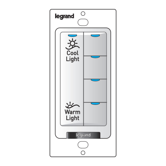
BUTTONS AND INDICATORS
Press and Hold to ramp
through CCT levels
The rocker LED is always ON if the LMSW-105-CCT is
bound to a load that is CCT enabled.
When the preset CCT Button level matches the CCT of the
DLM network, the LED will be bright.
LMPB-100
Power
Booster
LMRJ Cables
DLM Cable Connector
LMLM-101 Mounted on
Araya or Blanco Logic Module
NOTE: Each DLM local network must include a
DLM room controller, relay panel, or power booster
to supply low voltage power to the LMLM-101.
Blue Status LEDs
Preset CCT Buttons (4)
Configuration Button
(behind switch plate)
Red LED
120/277VAC
J-Box
LMFC-RJ
Red
Blue
Black
Advertisement
Table of Contents

Summary of Contents for wattstopper LMSW-105-CCT
-
Page 1: Specifications
Quick Start Guide • Guide de démarrage rapide • Guía de inicio rápido Catalog Number • Numéro de Catalogue • Número de Catálogo: LMSW-105-CCT Country of Origin: Made in China • Pays d’origine: Fabriqué en Chine • País de origen: Hecho en China SPECIFICATIONS This unit is pre-set for Plug n’... -
Page 2: Troubleshooting
4. All loads in the room turn OFF after entering PnL. After one second, one load turns ON. This is Load #1, which is bound to the LMSW-105-CCT paddle and all buttons as part of the Plug n’ Go factory default setting. -
Page 3: Instructions En Français
Pour connaître tous les détails opérationnels, les réglages et les fonctions supplémentaires du produit, consulter le guide d’installation du système Alimentation électrique ....Wattstopper contrôleur de pièce DLM fourni avec Wattstopper contrôleurs de pièce et aussi disponible au Connexion au réseau local DLM ........2 ports RJ-45 www.legrand.us/wattstopper. -
Page 4: Dépannage
4. Toutes les charges de la pièce s’ÉTEIGNENT en mode PnL. Une seconde plus tard, une charge s’ALLUME. Cette charge est la charge n° 1, qui est liée au pavé LMSW-105-CCT et aux boutons qui font partie des réglages d’usine par défaut du mode Plug n’ Go. La DEL bleue s’ILLUMINERA sur tous les boutons d’interrupteur, gradateurs et boutons d’ambiance liés à... -
Page 5: Instrucciones En Español
La ilustración siguiente muestra un ejemplo de cableado de topología libre. El Todas las cargas están Nivel de CCT predeterminado dispositivo LMSW-105-CCT se comunica con todos los demás dispositivos de vinculadas a todos los 100%K control de iluminación digital conectados a la red local DLM de bajo voltaje. -
Page 6: Solución De Problemas
4. Todas las cargas de la habitación se apagarán después de entrar a PnL. Después de un segundo, se encenderá una carga. Esta es la carga N.° 1, que está vinculada con la paleta del LMSW-105-CCT y con todos los botones como parte de la configuración predeterminada de fábrica de Plug n’ Go. El LED azul se mostrará...
Need help?
Do you have a question about the LMSW-105-CCT and is the answer not in the manual?
Questions and answers