Table of Contents
Advertisement
I
F
NTELLA
LEX
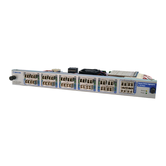
ACI-3030-T05-1 B
TAP/A
GGREGATOR
An all-in-one network monitoring solution
Fail-safe passive TAP in Bypass mode
5 Optical Bypass 1/10G switches
Up to 7 in-line appliance support
Heartbeat monitoring of appliance
Up to 14 monitoring tool ports
Monitor, aggregate and filter traffic
APCON, Inc. • www.apcon.com • +1 503-682-4050 • 800-624-6808
S
YPASS
WITCH
U
M
SER
ANUAL
A54-3002-050 • Rev B
Advertisement
Table of Contents

Summary of Contents for Apcon ACI-3030-T05-1
- Page 1 5 Optical Bypass 1/10G switches Up to 7 in-line appliance support Heartbeat monitoring of appliance Up to 14 monitoring tool ports Monitor, aggregate and filter traffic APCON, Inc. • www.apcon.com • +1 503-682-4050 • 800-624-6808 A54-3002-050 • Rev B...
- Page 2 APCON, Inc. reserves the right to revise this publication from time to time without obligation of APCON to notify any person or organization of such revision. APCON has prepared this manual for use by customers as a guide for proper installation, operation and maintenance of APCON equipment.
-
Page 3: Table Of Contents
APCON software products ........ - Page 4 Care of fiber optic cables ............. .68 Index ..............................71 APCON, Inc. A54-3002-027 • Rev B...
-
Page 5: Chapter 1: Preface
Chapter 1 Preface Chapter 1 ® This manual describes the APCON ACI-3030-T05-1 Bypass Switch (Bypass TAP). The Bypass TAP can be installed in any slot of any of the I XR chassis. NTELLA About this manual The information in this manual provides instructions on how to install, configure, and maintain the Bypass TAP. -
Page 6: Conventions In The Manual
Bypass Switch May be used interchangeably with “switch”, “chassis”, “hardware”, “blade” or “unit”. XR series May be referred to as XR series for brevity when referring NTELLA chassis to I XR chassis’ or blades. NTELLA APCON, Inc. A54-3002-027 • Rev B... -
Page 7: Apcon Software Products
OBILE ITAN management by providing a global view and real-time status of the APCON monitoring network. This allows technical staff to view and diagnose issues remotely at all times, thus reducing the time to resolve issues. The user-friendly interface provides network visibility, system and link status, alarm notifications, and log history. -
Page 8: Contact Apcon
Bypass Switch TAP/Aggregator User Manual Contact APCON To request technical assistance: • On the Web: APCON maintains an active website that contains current information about the company and sales office locations, new and existing products, sales contacts, service, documentation, and technical support information. -
Page 9: Chapter 2: Introduction
Introduction Chapter 2 Overview of features 9 Overview 10 ® This chapter introduces the features of the APCON Bypass Switch TAP/Aggregator (Bypass TAP). The Bypass TAP may be installed in any slot of an I XR chassis’ NTELLA (ACI-3036-XR, ACI-3072-XR, ACI-3144-XR, or ACI-3288-XR). -
Page 10: All-In-One Visibility
Ethernet. Systems can initially be installed as monitor only, then switched in-line when ready, making it easy to insert or remove in-line security tools. All-in-one visibility The Bypass TAP is part of APCON’s premier I XR network monitoring family, and is NTELLA compatible with all systems from 1RU to 8RU. -
Page 11: High Port Density
A network with multiple Bypass TAPs can be managed with T XR, a centralized management software solution with custom ITAN dashboards, reporting and batch upgrades along with the APCON M OBILE Basic operation The following description describes how the Bypass TAP switches from Monitor (Normal) mode... - Page 12 If the connection between the Bypass TAP and the network tool fails, the blade shifts into Bypass mode and redirects network traffic onto the user network as depicted below. This switching action to Bypass mode is referred to as failback. It is designed to prevent network traffic loss. APCON, Inc. A54-3002-027 • Rev B...
- Page 13 In a Load Balanced Group (LBG) configuration, a network outage would result in all of the traffic bypassing the Bypass TAP, just as occurs in a non-LBG configuration. The advantage in an LBG configuration is that if a loss of an in-line monitoring tool occurs, traffic destined for A54-3002-027 • Rev B APCON, Inc.
-
Page 14: Failback Method
In either event, W XR and/or T XR sends an alert notifying of the loss. If the ITAN APCON M is configured, the alert is also sent to those users who have been OBILE configured to receive alerts. Failback Method This release of the Bypass TAP supports two methods of failback recovery: •... -
Page 15: Automatic
1. A double-ended arrow is displayed across N1 and N2 ports, indicating the Network ports are now in Bypass mode. 2. The radio button for Port Mode is set to Bypass in the GUI. A54-3002-027 • Rev B APCON, Inc. -
Page 16: Failback Method
6. The List Alarms tab lists: • Port failback to Bypass mode • Port heartbeat lost 7. These alerts are sent to the T XR server and the APCON M ITAN OBILE Failback method The Bypass TAP supports both manual and automatic Failback Method. -
Page 17: Alarms
Monitor (Normal) mode are switched to Bypass mode and placed in alarm mode. • If the paired Network ports that are in alarm mode are set to Monitor (Normal) mode and heartbeats are sent and received properly, the alarms for those ports are cleared. A54-3002-027 • Rev B APCON, Inc. - Page 18 Chapter 2 Introduction Bypass Switch TAP/Aggregator User Manual APCON, Inc. A54-3002-027 • Rev B...
-
Page 19: Chapter 3: Specifications
Chapter 3 Specifications Chapter 3 This chapter provides the specifications relevant to the Bypass TAP. Specifications This section describes the specifications for the ACI-3030-T05-1 Bypass TAP . Physical interface The physical specifications for the Bypass TAP are as follows. Specification Description Dimensions 25”... -
Page 20: Electrical Specifications
The behavior of the LEDs for Power and Status displayed on the right side of the physical Bypass TAP is as follows LEDs Description Power LED • On Power is ON. • Off Power is OFF. APCON, Inc. A54-3002-027 • Rev B... -
Page 21: Port Leds
2 blades, up to 72 ports total ACI-3036-XR 1 blade, up to 36 ports total NOTE For any ACI-3288-XR chassis shipped before September 2014, please contact APCON Professional Services for separate upgrade instructions. When populated with I blades, these switches allow you to aggregate, filter, and NTELLA direct data to network monitoring and analysis equipment. -
Page 22: Blade/Chassis Compatibility
Chapter 3 Specifications Bypass Switch TAP/Aggregator User Manual Blade/Chassis compatibility Following is a list of APCON blades compatible with I chassis: NTELLA Chassis Compatibility Blade ACI-3036-XR ACI-3072-XR ACI-3144-XR ACI-3288-XR ACI-3011-E04-100 ACI-3030-E32-7 ... -
Page 23: Sfp Ports And Transceivers Supported
• ACI-0201-200-R (Single-Mode SFP+) NOTE Transceivers shipped in APCON products are Class 1 laser products. Manufacturer specifications state that these transceivers comply with regulations and are certified to meet the Class 1 eye safety requirements of EN (IEC) 60825 and electrical safety requirements of EN (IEC) 60950. - Page 24 Chapter 3 Specifications Bypass Switch TAP/Aggregator User Manual Following are the characteristics for SFP+ transceivers that can be ordered from APCON : Transceiver Transmit power (nominal) Receiver sensitivity ACI-0201-199-R –5.6 dBm to –3.0 dBm –5.4 dBm @ 10.5 Gbps Dual-Rate 1/10 Gbps...
-
Page 25: Chapter 4: Install And Configure The Unit
To avoid damage to hardware from ElectroStatic Discharge (ESD), always discharge any static electricity on your body by touching a grounded bare metal surface or an approved anti-static mat before picking up an ESD-sensitive electronic component. A54-3002-027 • Rev B APCON, Inc. -
Page 26: Protect Sensitive Devices
The chassis automatically detects when the blade is in place and powers on the blade. After adding a new blade or replacing an existing blade in a chassis, be sure to check for any available firmware updates ( refer to the W XR User Manual). APCON, Inc. A54-3002-027 • Rev B... -
Page 27: Web Xr Interface
LED. Appliance Ports When power is first applied, or when the user manually sets the port to Bypass mode, a gray heartbeat icon is displayed in the center of each port. A54-3002-027 • Rev B APCON, Inc. -
Page 28: Blade/Port Status
• Click a tab at the top of the window to select a blade. • Select a port on that blade by clicking on the icon for the port. The blade or port currently selected is highlighted in light blue. APCON, Inc. A54-3002-027 • Rev B... - Page 29 Additional Details Details on the SFPs installed in the port, including: Vendor Details Information about the transceiver installed in that port. Transmission Media Type, length, and so on. Supported Protocol Compliance Fibre Channel, Ethernet, SONET/SDH. A54-3002-027 • Rev B APCON, Inc.
-
Page 30: Check Cable Signal Strength
No signal, or cables are not plugged in. Signal strength is out of range. Green Signal strength is within range. 3. Continue to select ports from the Blade/Port Status window to view the signal strength for each port. APCON, Inc. A54-3002-027 • Rev B... -
Page 31: Port Statistics Overview
2. On the Ports page, click the soft arrow at the lower right corner of a port to display the Blade/Port Status window. 3. In the Alarms section, check the slider for Alarm Notification. The default position is Off: A54-3002-027 • Rev B APCON, Inc. -
Page 32: View Bandwidth Thresholds For Ports
XR and click the soft arrow for the Global View icon. From the pop-up menu, select Ports. 2. On the port that displays a warning indicator in red, click the soft arrow at the lower right corner of the port to display the Blade/Port Status window. APCON, Inc. A54-3002-027 • Rev B... -
Page 33: Sfp Additional Details
Click the arrow for Vendor Details to view additional information about the SFP manufacturer. Transmission media supported Click the arrow for Transmission Media Supported to view additional information about the media for the SFP. A54-3002-027 • Rev B APCON, Inc. -
Page 34: Protocol Compliance
• Using the pop-up menu for a port (select Diagnostics > Port Statistics), which displays the following tabs: • Rate Information • Port Statistics • RMON EtherStats For information about using Port Statistics to resolve issues with oversubscription, refer to Using Port Statistics in the XR User Manual. APCON, Inc. A54-3002-027 • Rev B... -
Page 35: Port Properties
Each of the settings are described in the sections that follow. Right-click on an Appliance port and select Port Properties from the pop-up menu, the following window is displayed. Each of the settings are described in the sections that follow. A54-3002-027 • Rev B APCON, Inc. -
Page 36: View Options For Port Properties
3. By default, all boxes are checked. Click the checkboxes to deselect any settings not desired. This toggles the respective information in the Port Properties window for all blades. This is not the same menu as the View Options for the Ports page. APCON, Inc. A54-3002-027 • Rev B... -
Page 37: Port Name
Bypass mode causing the network traffic to be redirected back onto the user network (refer to Basic operation on page 11). Port pairing is denoted graphically with a dark-blue outline around the paired ports, as shown in the following image. A54-3002-027 • Rev B APCON, Inc. -
Page 38: Paired Port Rules
• Port Name • Set Bandwidth Thresholds The following screen image depicts a LBG bypass aggregation from Network paired ports A1N1/A1N2 to six pair of Appliance ports: • A1A1/A1A2 • A2A1/A2A2 • A3A1/A3A2 • A4A1/A4A2 APCON, Inc. A54-3002-027 • Rev B... -
Page 39: Activate/Remove A Trunk Port
4. From the pop-up menu, choose Deactivate Trunk. 5. The trunk is disconnected and the icon is removed from the port. 6. Repeat the above steps for the ingress port on the second chassis used for trunking. A54-3002-027 • Rev B APCON, Inc. -
Page 40: Port Profiles
That feature can help to avoid dropping packets on egress ports. The Enhanced Port Profile feature is available on the ACI-3030-T05-1 Bypass TAP used in XR chassis. This feature should not be used on links that are constantly oversubscribed. This setting is typically used to avoid packet drop issues, and is intended only for use when there are intermittent bursts of traffic. - Page 41 5. Click Save. IMPORTANT If the Enhanced Profile feature is selected but is then not effective, it is recommended to change the setting back to the Default Profile. A54-3002-027 • Rev B APCON, Inc.
-
Page 42: Port Rates
In this case, changing port rates takes approximately 90 seconds. Wait this amount of time to ensure that port rates are in sync in both W and in CLI. APCON, Inc. A54-3002-027 • Rev B... -
Page 43: Set Bandwidth Threshold Per Port
XR and click the soft arrow for the Global View icon. From the pop-up menu, select Ports. 2. On the Ports page right-click the Appliance or standard I port to pair or unpair NTELLA and select Port Properties. A54-3002-027 • Rev B APCON, Inc. - Page 44 3. Go to the Paired Ports area. 4. Click the slider to pair the selected port with the adjacent port. The indicator turns green, the selected port and adjacent port are outlined in a blue border. 5. Click Save. APCON, Inc. A54-3002-027 • Rev B...
-
Page 45: Network Port Settings (Network Ports)
5. By default Network ports are set to Bypass. When connected in an aggregation the port switches to Monitor (Normal). 6. To set the selected port to Monitor, click the radio Monitor (Normal) radial button. A54-3002-027 • Rev B APCON, Inc. -
Page 46: Heartbeat (Appliance Ports)
The heartbeat can be enabled, or disabled, independently of the Port Mode setting (refer to Network port settings (Network ports) on page 45). For example, Monitor mode can be enabled without enabling the heartbeat. The heartbeat cannot be enabled unless the Appliance ports are paired. APCON, Inc. A54-3002-027 • Rev B... - Page 47 Sent packets considered for a (See Note) considered for a failover Condition. failover Condition. NOTE If Monitor Mode is set to Link, the Internal and Failover Condition sliders are grayed out. A54-3002-027 • Rev B APCON, Inc.
- Page 48 Set the Sent slider to the desired number of heartbeats to be sent during the specified interval. The default is 5. The range is 1 to 10. v. Click the Enable slider to activate the heartbeat. APCON, Inc. A54-3002-027 • Rev B...
-
Page 49: Port Locking
XR and click the soft arrow for the Global View icon. From the pop-up menu, select Ports. 2. On the Ports page, select a port and click the soft arrow. 3. From the pop-up menu, select Port Properties. A54-3002-027 • Rev B APCON, Inc. - Page 50 1. Go to W XR and click the soft arrow for the Global View icon. From the pop-up menu, select Ports. 2. On the Ports page, select a port and click the soft arrow. APCON, Inc. A54-3002-027 • Rev B...
- Page 51 4. Go to the section for Port Locking. 5. Click the button for Lock Port to turn OFF Port Locking. 6. Click Save. This removes the lock and clears any messages associated with the previously locked port. A54-3002-027 • Rev B APCON, Inc.
- Page 52 Chapter 4 Install and configure the unit Bypass Switch TAP/Aggregator User Manual APCON, Inc. A54-3002-027 • Rev B...
-
Page 53: Chapter 5: Aggregation Examples
(refer to Paired ports on page 43). 1. On the W XR Global View > Port screen, click a Network port within a segment and select Duplex Pair. 2. Click Set. A54-3002-027 • Rev B APCON, Inc. - Page 54 4. Click Confirm. The Confirm Connection pop-up window displays. The Network port B1N1 has a duplex aggregation to the Appliance port B1A1. The Network port B1N2 has a duplex aggregation to the Appliance port B1A2. APCON, Inc. A54-3002-027 • Rev B...
-
Page 55: Creating A Bypass Aggregation Between Two Different Segments
XR Global View > Port screen, click a Network port within a segment and select Duplex Pair. This action highlights both of the Network ports in the segment with the color yellow. 2. Click Set. 3. Click an Appliance port in a different segment. A54-3002-027 • Rev B APCON, Inc. - Page 56 The Network port H5N2 has a duplex aggregation to the Appliance port H4A2. 5. If desired, enter an optional Patch Name, Job Ticket and/or Message. 6. Click Save. A bypass aggregation between two segments is configured. APCON, Inc. A54-3002-027 • Rev B...
-
Page 57: Creating A Bypass Aggregation That Includes A Load Balanced Group
XR Global View > Port screen, click a Network port within a segment and select Duplex Pair. This action highlights both of the Network ports in the segment with the color yellow. 2. Click Set. 3. Click Load Balance. The Create Load Balance Group pop-up window displays. A54-3002-027 • Rev B APCON, Inc. - Page 58 9. On the Ports screen, the new LBG icon ( ) is displayed on the left side of each Appliance port that is part of the LBG. 10. On the Ports screen, click Confirm. The Confirm Connection pop-up window displays. APCON, Inc. A54-3002-027 • Rev B...
- Page 59 If a port fails in an LBG, and there are other ports in the LBG that can assume the load for the failed port, the blade does not shift the Network ports for the LBG into Bypass mode. 13. A bypass aggregation including a Load Balance Group is created. A54-3002-027 • Rev B APCON, Inc.
-
Page 60: Failover Recovery
Failover recovery GUI for manual and automatic From the GUI standpoint, to implement both the Manual and Automatic recovery features, a pair of radio buttons are added in the Port Properties window on the Heartbeat panel. APCON, Inc. A54-3002-027 • Rev B... -
Page 61: Implementing Controls For Detecting Externally Inserted Heartbeat Packets
Bypass mode. The following diagram depicts the network tool sending heartbeat packets to the Bypass Switch blade using the Tx lines. A54-3002-027 • Rev B APCON, Inc. -
Page 62: Monitor Modes
• This option has nothing to do with an external device inserting heartbeat packets into a data stream. However, it does offer another method for the blade to monitor availability of the device connected to the Appliance ports. APCON, Inc. A54-3002-027 • Rev B... - Page 63 As a system safeguard, back up both the configuration data and user settings before performing any maintenance, upgrade, or service. For step-by-step instructions on how to back up data, refer to the W XR User Manual. A54-3002-027 • Rev B APCON, Inc.
-
Page 64: Chapter 6: Maintenance
The chassis automatically detects when the blade is in place and powers on the blade. After adding a new blade or replacing an existing blade in a chassis, be sure to check for any available firmware updates ( refer to the W XR User Manual). APCON, Inc. A54-3002-027 • Rev B... -
Page 65: Remove A Blade
2. Unscrew the thumbscrews on both sides of the blade. 3. Hold the blade straight and gently pull it straight out, as shown in the following illustration. Do not twist or bend the blade. A54-3002-027 • Rev B APCON, Inc. -
Page 66: View Blade Status
♦ To view the status information of a blade: 1. Go to W XR and select the System page and click the graphic for the front view. 2. Click the desired blade. The status dialog for the selected blade displays. APCON, Inc. A54-3002-027 • Rev B... - Page 67 Displays warnings for transceivers Transceiver Displays alarm conditions for transceivers. For details about the colors, see below. Type Lists the type of APCON blade. Model Lists the model number for the installed blade. Serial Number Lists the serial number for the installed blade.
-
Page 68: Care Of Fiber Optic Cables
1. Grasp the connector while squeezing the connector housing, and gently pull to disconnect the connector from the port. CAUTION Transceivers shipped in APCON chassis’ are Class 1 laser products. To avoid exposure to low-level laser radiation, do not stare into any open apertures of the ports when cables are not connected. - Page 69 6. Discard unused tissues or swabs properly. Never reuse any cleaning pad, swab or tissue. 7. Remove the dust cover immediately prior to inserting the cable. 8. Connect the cable by gently inserting it into the transceiver. A54-3002-027 • Rev B APCON, Inc.
- Page 70 Chapter 6 Maintenance Bypass Switch TAP/Aggregator User Manual APCON, Inc. A54-3002-027 • Rev B...
-
Page 71: Index
Chapter 1: Index Index Chapter 1 chassis install blade About APCON software replace blades ACI-3030-T05-1 check signal strength blade Class 1 laser products add Port Name clean connectors adjust bandwidth threshold CLI software aggregated connections compatibility Enhanced Port Profile transceivers supported... - Page 72 Lock icon Appliance Port Properties locking displayed about Enhanced Profile ports full-duplex time limit line rates unlocking lock locking Network Port Properties Profile maintenance set bandwidth thresholds back up first unlocking cable test view names APCON, Inc. A54-3002-027 • Rev B...
- Page 73 XML-restricted characters supported trunking SFPs enable/activate a trunk port dual-rate transceivers turn power off signal TX signal receive (RX) signal strength soft arrow software, APCON products unlock specifications ports electrical user manual, contents operations A54-3002-027 • Rev B APCON, Inc.
- Page 74 Index Bypass Switch TAP/Aggregator User Manual View Options Port Properties website for APCON XR software weight of blade restricted characters APCON, Inc. A54-3002-027 • Rev B...
Need help?
Do you have a question about the ACI-3030-T05-1 and is the answer not in the manual?
Questions and answers