Table of Contents
Advertisement
Quick Links
Advertisement
Table of Contents

Related Manuals for Radio Active Designs UV-1G

Summary of Contents for Radio Active Designs UV-1G
- Page 1 UV-1G IRELESS NTERCOM YSTEM ANUAL Rev. G Dec-2017...
- Page 2 This page intentionally left blank. UV-1G User Manual Rev. G 2 of 90...
- Page 3 UV-1G User Manual Rev. G 3 of 90...
- Page 4 (2) this device must accept any interference received, including interference that may cause undesired operation. • Per FCC 15.21: Changes or modifications not expressly approved by Radio Active Designs could void the user's authority to operate the equipment. UV-1G User Manual Rev. G...
-
Page 5: Table Of Contents
Info Screen ........................38 Enabling/Disabling the Passcode .................. 38 Changing the Passcode ....................39 Base Station Gain Adjustments ....................40 Intercom 1 & 2 ......................40 Auxiliary ........................40 Stage Announce......................41 UV-1G User Manual Rev. G 5 of 90... - Page 6 Base Station Tab........................65 Receivers ........................65 Using Shortcut Keys ...................... 66 Routing ........................66 Transmitters ......................... 67 Intercoms ........................67 Gains ..........................68 UI Display Settings ......................69 Passcode Enable ......................69 UV-1G User Manual Rev. G 6 of 90...
- Page 7 Software Preferences ........................ 81 On Start-Up ........................81 Software Updates ......................81 Permit Use of Channel 37 ......................82 Device Info ..........................82 Base Station Info ......................82 Belt Pack Info ....................... 82 UV-1G User Manual Rev. G 7 of 90...
- Page 8 About RAD UV-1G ........................83 Use of Open Source Software ....................83 Appendix A .......................... 84 2W Pin out........................84 4w pin out ........................85 Troubleshooting & FAQs ...................... 86 UV-1G User Manual Rev. G 8 of 90...
-
Page 9: Table Of Figures
ABLE OF IGURES FIGURE 1 UV-1G FRONT PANEL BUTTONS ......................15 FIGURE 2 FRONT PANEL LED DESCRIPTIONS ......................17 FIGURE 3 BASE STATION REAR PANEL ........................19 FIGURE 4 BELT PACK TOP VIEW ..........................20 FIGURE 5 BELT PACK SIDE VIEWS ..........................21 FIGURE 6 BELT PACK BOTTOM VIEW ........................ -
Page 10: Features
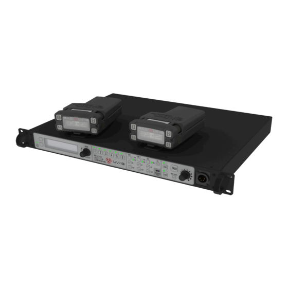
ENERAL NFORMATION The Radio Active Designs® UV-1G is a two-channel full-duplex UHF/VHF wireless intercom system that utilizes up to six wireless Belt Pack units per Base Station. Each Belt Pack is capable of simultaneous Talk and Listen on two separate audio channels. -
Page 11: Downloads / Manuals
Manuals UV-1G Manual (this document) Dimensions Belt Pack Dimensions Battery Dimensions ECHNICAL UPPORT Please contact technical support for direct assistance. Monday – Friday 8 am – 6 pm PST technicalsupport@radioactiverf.com Phone: 402.477.0695 UV-1G User Manual Rev. G 11 of 90... -
Page 12: Uv-1G Specifications
RF Frequency Stability ±1.5ppm Occupied Bandwidth 25 kHz Radiated Harmonics and Spurious Exceeds FCC Requirements ECEIVER Type Direct Conversion RF Sensitivity -110dBm for 12dB SINAD Squelch Threshold Automatic IF Selectivity 25 kHz UV-1G User Manual Rev. G 12 of 90... - Page 13 RF Frequency Stability ±1.5 ppm Distortion <1% at full modulation UV-1G User Manual Rev. G 13 of 90...
-
Page 14: System Diagram
YSTEM IAGRAM UV-1G User Manual Rev. G 14 of 90... -
Page 15: Base Station
TATION RONT ANEL UTTON ESCRIPTIONS Figure 1 UV-1G Front Panel Buttons 1. POWER BUTTON Momentary press to power up unit Press and hold to power off 2. SOFT KEY 1 Menu Navigation Variable button function 3. SOFT KEY 2 Menu Navigation Variable button function 4. - Page 16 The Program Port is a USB Micro-B compatible port that is used for configuring UV-1G Base Stations and Belt Packs or upgrading firmware via the UV-1G PC Application. For convenience, the UV-1G Belt Pack will power on when the cable is plugged in and connected to a PC, the Base Station will not.
-
Page 17: Front Panel Led Description
17. AUXILIARY ENABLE LED Green = Enabled Red = Over Modulation Off = Disabled 18. LOCAL HEADSET CHANNEL 1 ENABLE LED Green = Enabled Off = Disabled 19. LOCAL HEADSET CHANNEL 1 STATUS LED UV-1G User Manual Rev. G 17 of 90... - Page 18 Green = Local headset traffic on Channel 2 (Talk button pressed, local headset Channel 2 enabled) Red = Over modulation Off = No traffic 22. POWER / FAN FAIL LED Green = System powered up Red = Fan failure condition UV-1G User Manual Rev. G 18 of 90...
-
Page 19: Rear Panel Description
14. Stage Announce Relay Contact 15. Stage Announce XLR 3-pin audio output 16. DC Power Input 17. Transmit Antenna 1 or 1 & 2 combined (BNC) NOTE: See Appendix A for XLR pin out. UV-1G User Manual Rev. G 19 of 90... -
Page 20: Belt Pack
At Home Screen: Push to transmit on User-configured Channel (1+2, WTA 1, WTA 2, WTA 1+2, SA, Aux) In Menu: Functions as “soft key” described on the LCD • TALK / OVER MODULATION LED FOR THE PROGRAMMABLE 2 TALK BUTTON UV-1G User Manual Rev. G 20 of 90... -
Page 21: Figure 5 Belt Pack Side Views
At Home Screen: Adjusts Headset volume for Channel 1 In Menu: Navigation; changing values 9. POWER / MENU BUTTON Momentary press turns Belt Pack on; toggles Menu Press and hold turns OFF UV-1G User Manual Rev. G 21 of 90... -
Page 22: Figure 6 Belt Pack Bottom View
Figure 6 Belt Pack Bottom View 10. HEADSET CONNECTOR Four Pin XLR male (shown); Five Pin XLR female 11. BATTERY LATCH 12. REMOVABLE BELT CLIP UV-1G User Manual Rev. G 22 of 90... -
Page 23: Quick Start Guide
LEDs. Press and hold the power button to power off. 5. TX & RX FREQUENCIES: Program the transmitter and receiver frequencies as desired. See the UV-1G PC Application (supplied) for information on how to program frequencies from the Base Station itself. -
Page 24: Belt Pack
Base Station defaults for one Belt Pack (Belt Pack #1). The other Belt Packs will need their frequencies changed from the defaults. CONGRATULATIONS, YOUR NEW UV-1G IS READY FOR USE! UV-1G User Manual Rev. G 24 of 90... -
Page 25: Base Station Operation
To turn the Base Station off, press and hold the POWER button until the LCD screen goes blank. CREEN The Home Screen is the root of the UV-1G Base Station UI. It displays information regarding transmitter power level, receiver status, Base Station link mode, and local headset status. The left portion of the screen provides links to the main menu and RSSI screens. -
Page 26: Receiver Status
36 Belt Packs can be used in a single wireless two-channel system. The Base Station Link Mode status appears on the Home Screen above the power level indication for transmitter 1 (T1). The letter M stands for Master and S for Slave. UV-1G User Manual Rev. G 26 of 90... - Page 27 Whenever the external clock is present, the internal electronics will automatically switch to using this reference. This clock switching is independent of master/slave operation. UV-1G User Manual Rev. G 27 of 90...
-
Page 28: Local Headset Status
MENU..T2 50mW...R3 OFF..R6 W1 RSSI..HS: OFF BACK RSSI R5 OFF BACK R6 OFF The RSSI screen, shown above, displays the signal strength of each receiver. OFF means that particular receiver is disabled. UV-1G User Manual Rev. G 28 of 90... -
Page 29: Base Station Menu Structure
• From home screen, press MENU, scroll to RX SETTINGS, press SELECT. The screen will appear as follows: .... 175.000 ..R2: 200.000 BACK..R3: 202.000 This screen displays the frequency (in MHz) of all six receivers. UV-1G User Manual Rev. G 29 of 90... - Page 30 • Use the encoder to change the selection and press SAVE to save the change..R1 Freq : 175.000 SAVE..R1 Freq : 175.000 ..Status: Status: Enabled ..Status: Enabled Enabled Select ....Down BACK..BACK..UV-1G User Manual Rev. G 30 of 90...
-
Page 31: Advanced Receiver Settings
• Input attenuation options are 0dB, 5dB, 10dB, and 20dB. • Press SAVE to save the change or BACK to cancel. To access the Rx Routing Settings, select it from the ADVANCED RX SETTINGS sub-menu within the main menu. UV-1G User Manual Rev. G 31 of 90... - Page 32 Use the encoder to change the value. • Options are Enbld (for enabled) and Dsbld (for disabled). Press SAVE to save the change or BACK to cancel. • The following table shows the settings for common routes: UV-1G User Manual Rev. G 32 of 90...
-
Page 33: Aux In Settings
COM2 Aux In Mode: ..COM2.Aux.In.Mode: ..BACK..Down • Use the encoder to change the value. o Options are Off, Local, and Global. • Press SAVE to save the change or BACK to cancel. UV-1G User Manual Rev. G 33 of 90... -
Page 34: Transmitter Settings
• Press SAVE to save the change or BACK to cancel..T1...Power : 100mW SAVE..T1...Power : 100mW Freq ....Freq 96.000 ..... 4 96.000 Select ..... Status : Enabled ....Status: Enabled Down BACK..BACK..UV-1G User Manual Rev. G 34 of 90... -
Page 35: Local Headset Options
Status T /L SAVE..Status Select BACK..Earphones : Combined BACK..Earphones : Combined BACK..BACK..Down Down ..Status : T/L SAVE..Status :.T/L BACK....Earphones : Combined Select BACK..Earphones : Combined BACK..BACK..Down UV-1G User Manual Rev. G 35 of 90... -
Page 36: Display Setting
Options: 5S for 5 seconds 10S for 10 seconds 20S for 20 seconds 30S for 30 seconds 60S for 60 seconds ON meaning it will never turn off. UV-1G User Manual Rev. G 36 of 90... - Page 37 • Turn the encoder as shown above. • Press SAVE to save the change or press BACK to ignore it. NOTE: The contrast updates in real time as it is modified. LED Brightness UV-1G User Manual Rev. G 37 of 90...
-
Page 38: Base Station Link Modes
Link Settings: Master Select Info BACK The Info screen is located in the menu right below LINK SETTINGS. • To view the screen, press SELECT as shown above. NABLING ISABLING THE ASSCODE UV-1G User Manual Rev. G 38 of 90... -
Page 39: Changing The Passcode
Passcode: Disabled Select MENU..0..*..*..* ..Change Passcode BACK..Save SAVE..Re-enter New Passcode: MENU..MENU..0..*..*..* BACK..Save Save EXIT..BACK..MENU..Passcode .Changed. MENU..Error: Passcodes don’t MENU..MENU..match. BACK..BACK..UV-1G User Manual Rev. G 39 of 90... -
Page 40: Base Station Gain Adjustments
SAVE...COM 1 Input Gain Down BACK... The figure above shows an example of the Intercom gain screen. UXILIARY SAVE...Aux Input Gain Down BACK... The figure above shows an example of the Auxiliary gain screen. UV-1G User Manual Rev. G 40 of 90... -
Page 41: Stage Announce
TAGE NNOUNCE SAVE...SA Gain Down BACK... The figure above shows an example of the Stage Announce gain screen. UV-1G User Manual Rev. G 41 of 90... -
Page 42: Base Station Local Headset
UTTON The Talk button allows the Base Station user to talk on the Intercoms. The button can be pressed and held or “tapped” to latch on and off. UV-1G User Manual Rev. G 42 of 90... -
Page 43: Belt Pack Operation
To turn the Belt Pack on, press the power button as shown in Figure 8 above. While the Belt Pack is powering on, a splash screen will be displayed. RADIO ACTIVE DESIGNS . . . Once the Belt Pack is ready for use, the home screen will be displayed. UV-1G User Manual Rev. G 43 of 90... -
Page 44: Powering Down
Each talk button has a green and red LED set. The green LED turns on to show that the transmitter is active. The red LED turns on when microphone over modulation occurs while transmitting. UV-1G User Manual Rev. G 44 of 90... -
Page 45: Transmit Status Indicators
• When on, press and hold (approximately 3 seconds) to turn it off. • To get into or out of the menu, when the Belt Pack is on, press (without holding) the button. UV-1G User Manual Rev. G 45 of 90... -
Page 46: Belt Pack Menu Structure
BLGHT: backlight will be disabled or blacked out. • To change the blackout mode, press SELECT. • Turn either encoder as shown above. • Press SAVE to save the change or BACK to ignore it. UV-1G User Manual Rev. G 46 of 90... - Page 47 • To change the brightness, press SELECT. • Turn either encoder as shown above. • Press SAVE to save the change or BACK to ignore it. NOTE: Brightness updates in real time as it is modified. UV-1G User Manual Rev. G 47 of 90...
- Page 48 • To change the brightness, press SELECT. • Turn either encoder as shown above. • Press SAVE to save the change or BACK to ignore it. NOTE: The brightness updates in real time as it is modified. UV-1G User Manual Rev. G 48 of 90...
-
Page 49: Advanced Settings
If it is incorrect Invalid Passcode will be display for three seconds before returning to the main menu..Invalid .Passcode Manage Scenes Tx Settings BACK Passcode incorrect Passcode correct, Advanced Settings See ENABLING/DISABLING THE PASSCODE and/or CHANGING THE PASSCODE for more information. UV-1G User Manual Rev. G 49 of 90... -
Page 50: Manage Scenes
Z), Lower Case Letters (a-z), Numbers (0-9), and Symbols (SYM). o Press SELECT to change the selected character. o Press SAVE to save the changes or BACK to ignore them. .CENEA SCENEA Select SCENEB REMOVE .... BACK SAVE..[A-Z]..BACK UV-1G User Manual Rev. G 50 of 90... - Page 51 (Disabled option). This allows for a quick and easy way to switch between scenes. UV-1G User Manual Rev. G 51 of 90...
- Page 52 BACK • To change the frequency, scroll down to box FREQ: press SELECT and the first frequency digit will be boxed (see below). • Use either encoder to change the boxed digit UV-1G User Manual Rev. G 52 of 90...
- Page 53 The receiver settings allow the user to change the receiver frequencies as well as enable/disable them. The receiver settings are located in the ADVANCED SETTINGS sub-menu. Once selected, the screen will appear as follows: UV-1G User Manual Rev. G 53 of 90...
- Page 54 Turn off an un-needed receiver to save battery power. • To change the status, scroll down to box Status and press SELECT. • Turn the encoder to change the selection • Press SAVE to save the change. UV-1G User Manual Rev. G 54 of 90...
- Page 55 The right encoder changes the group. There are four groups: Upper Case Letters (A- Z), Lower Case Letters (a-z), Numbers (0-9), and Symbols (SYM). o Press SELECT to change the selected character. UV-1G User Manual Rev. G 55 of 90...
- Page 56 The Rx Attenuation menu option in the Advanced Settings sub-menu allows the user to set some RF front-end attenuation for the receivers. This parameter can be set to 0dB (default), 5dB, 10dB, 15dB, and 20dB. This applies to both receiver channels. UV-1G User Manual Rev. G 56 of 90...
- Page 57 If Combined is chosen, audio for both receivers will be routed to both earphones. Note: if only one receiver is enabled then audio to that receiver will be routed to both earphones no matter what headset option is chosen. UV-1G User Manual Rev. G 57 of 90...
- Page 58 Min.Vol..:..1 .P1234 ..BP ID :..BP1 Select BACK SAVE..[A-Z]..BACK • To change the ID, press SELECT. • The left encoder changes the currently selected character. • The right encoder changes the group. UV-1G User Manual Rev. G 58 of 90...
- Page 59 SAVE BACK To enable/disable passcode, access the ADVANCED SETTINGS sub-menu. • Select PASSCODE. • To change the setting, press SELECT. • Turn the encoder until the desired option appears. • Press SAVE. UV-1G User Manual Rev. G 59 of 90...
-
Page 60: Microphone Gain
• Press SAVE to save the change or BACK to ignore it. ICROPHONE To change the headset microphone gain, access the Menu from the Home Screen. • Press the right soft key showing MIC G. UV-1G User Manual Rev. G 60 of 90... - Page 61 The bar graphic (1-11) and a number (1-32) will show the current value of the microphone gain. The gain is “live” meaning it will change as the user changes it. • Press SAVE to save the change, and BACK to ignore any changes and return to the menu UV-1G User Manual Rev. G 61 of 90...
-
Page 62: Pc App
PC A VERVIEW The Radio Active Designs UV-1G PC Application provides the user with ability to update and inspect the configuration of the Base Station or Belt Pack. Additionally, it provides the ability to update the firmware in 1G devices. The communication between the Base Station or Belt Pack and UV-1G PC application utilizes USB. -
Page 63: Menus
The Passcodes command presents the Passcodes dialog to set and enable passcodes for the Base Station and Belt Packs. The Button Labels command presents the Button Labels dialog to specify the pick list of button labels for the Belt Packs. UV-1G User Manual Rev. G 63 of 90... -
Page 64: The Scenes Menu
The Show Device Info command presents the Base Station or Belt Pack Info dialogs for all connected devices. The RAD UV-1G Help command shows the online help system. The About RAD UV-1G command shows the About Radio Active Designs UV-1G dialog. OPUP REQUENCIES... -
Page 65: Base Station Tab
Intercoms, Gains, UI Display Settings, Base Station Mode, and Mic & Headset Settings. ECEIVERS The receiver settings allow the user to change the receiver frequencies, as well as enabling or disabling them. UV-1G User Manual Rev. G 65 of 90... -
Page 66: Using Shortcut Keys
Ctrl key while pressing V (Ctrl-V). If several frequencies are copied, each one on a separate line, the user can paste them all it at once. OUTING UV-1G User Manual Rev. G 66 of 90... -
Page 67: Transmitters
A transmitter may be disabled if it is not needed. Lock Status While the Base Station is connected the Lock Status is continually updated. NTERCOMS Each Base Station can connect to two intercom systems. UV-1G User Manual Rev. G 67 of 90... -
Page 68: Gains
Input and Output gains range from 0 (off) to 32 (maximum). Auxiliary Input and Output gains range from 0 (off) to 32 (maximum). Stage Announce Output gain ranges from 0 (off) to 32 (maximum). UV-1G User Manual Rev. G 68 of 90... -
Page 69: Ui Display Settings
Belt Pack audio data to the master unit. In effect, this means that up to 36 Belt Packs can be used in a single wireless two-channel system. UV-1G User Manual Rev. G 69 of 90... -
Page 70: Mic & Headset Settings
All of the Base Station's current settings will be read into the Base Station Tab. Write to the Base Station. All of the Base Station Tab's current settings will be written (programmed) into the Base Station. UV-1G User Manual Rev. G 70 of 90... -
Page 71: Belt Packs Tab
A Scene consists of all Belt Pack settings except Id, Display, and Passcode settings. Each Belt Pack can store up to 10 different scenes. Uses the Scenes menu to Add, Remove, and Rename Scenes. UV-1G User Manual Rev. G 71 of 90... -
Page 72: Receiver One And Receiver Two
Copy frequencies out of an email or other document and paste them into the frequency fields by holding down the Ctrl key while pressing V (Ctrl-V). If several frequencies are copied, each one on a separate line, the user can paste them all it at once. UV-1G User Manual Rev. G 72 of 90... -
Page 73: Button Labels
Button 1, Button 2, Button 3, Button 4 Options include Disabled, PTT, and Latch. OUBLE CTION Button 1, Button 2, Button 3, Button 4 Options include Disabled, Scenes selection, and switch to the selected scene. UV-1G User Manual Rev. G 73 of 90... -
Page 74: Battery Settings
Options range from 1 (dim) to 5 (bright). Passcode If enabled, the user will be required to enter the passcode before making changes via the menus. & H EADSET Mic Gain The gain can be from 1 to 11. UV-1G User Manual Rev. G 74 of 90... -
Page 75: Master Volume
The Program button brings up the Write to Belt Packs dialog. ONNECTED When a Belt Pack is connected via USB, select the Belt Pack Row to associate it with, and action to take: Read from the Belt Pack. UV-1G User Manual Rev. G 75 of 90... -
Page 76: Add Scene
Enter a name for the Scene. Scene names can be up to six characters in length. Add to... Select one or more Belt Packs to add a scene. EMOVE CENES Select one or more Scenes to remove from one or more Belt Packs. UV-1G User Manual Rev. G 76 of 90... -
Page 77: Rename Scenes
Configured ID This is the Belt Pack Row's ID which may not match that of the Belt Pack with which it is associated. IAGNOSTICS This window displays in real time the logging output. UV-1G User Manual Rev. G 77 of 90... -
Page 78: Passcodes
A Base Station or Belt Pack can be passcode protected to prevent the user from making changes via the front panel UI. A passcode consists of four digits 0 through 9. Enabling Passcodes Passcode checking can be enabled or disabled. UV-1G User Manual Rev. G 78 of 90... -
Page 79: Button Labels
Click the right arrows to copy to all columns. Click the top right arrow to copy all rows to all columns. RITE ACKS Allows the user to automatically write to (program) all Belt Packs one after another. UV-1G User Manual Rev. G 79 of 90... -
Page 80: Device Firmware Update
4) As soon as that Belt Pack is written, disconnect it and connect to the next Belt Pack. 5) Continue until all Belt Packs have been written. EVICE IRMWARE PDATE TATION IRMWARE IRMWARE UV-1G User Manual Rev. G 80 of 90... -
Page 81: Automatic Updates
Choose whether to automatically open the last saved configuration file on start-up. OFTWARE PDATES Choose whether to have the software automatically check for updates, and how often to do so. Check for updates manually by clicking the "Check for update now" link. UV-1G User Manual Rev. G 81 of 90... -
Page 82: Permit Use Of Channel 37
Enable frequencies in channel 37. Check the check box to enable, or un-check it to disable, frequencies in channel 37. Enter the passcode: To enable frequencies, the user will need to obtain a passcode from Radio Active Designs technical support. EVICE Information will be displayed for all connected devices, one device at a time. -
Page 83: About Rad Uv-1G
3 or later. Usb4java is an implementation of the javax.usb standard produced by (JSR 80). Usb4java depends upon commons-lang3 version 3.2.1, licensed under The Apache Software License, Version 2.0. This software also uses Gson version 2.3.1, licensed under the Apache 2.0 License. UV-1G User Manual Rev. G 83 of 90... -
Page 84: Pin Out
Common Audio 1 1 – Common Male Female 2 – Audio 1 Jack Jack 3 – Audio 2 Audio 2 NOTE: DC power is not supplied – audio pins are AC coupled. UV-1G User Manual Rev. G 84 of 90... -
Page 85: 4W Pin Out
In Minus Out Minus Out Plus In Plus No Connect 3 – In Plus 4 – Out Plus 5 – Out Minus 6 – In Minus NOTE: Jack is RJ-11 and RJ-45 compatible. UV-1G User Manual Rev. G 85 of 90... -
Page 86: Troubleshooting & Faqs
In the stand-alone mode of operation, one may place a whip antenna directly on to the rear panel BNC of the unit. In this case, one would place the UV-1G in to “Combined” mode. If you are deploying any transmitter combiner you must place the switch in to the “Separate” mode. This will place the two internal transmitters on to both BNC RF output connections on the rear panel. - Page 87 Details: Using the Sync cable on the rear panel of the Radio Active Designs UV-1G base station opens a world of possibilities. When all your base stations are synchronized with each other, any belt pack may be tuned across any two transmitter channels regardless of which set of base stations the transmitters are tuned to.
- Page 88 AM signal is an active electronics circuit; even one that is not related to RF in the least. In addition, our RAD UV-1G uses direct conversion meaning that there is no Intermediate Frequency. The RF signal IS the audio signal. This is why you hear some form of the audio being transmitted on the base station.
- Page 89 RAD recommends the user to wear a two-way radio on the OPPOSITE side of the RAD pack to avoid interference between each other. The 2-way Radio transmission can potentially damage the receiver board in the RAD pack if it is a few inches in proximity. UV-1G User Manual Rev. G 89 of 90...
- Page 90 This page intentionally left blank. UV-1G User Manual Rev. G 90 of 90...
Need help?
Do you have a question about the UV-1G and is the answer not in the manual?
Questions and answers