Table of Contents
Advertisement
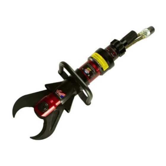
SLC-24, SLC-28, SLC-29
& BFC-320
CUTTER
Operations Manual
SLC-24
SLC-28
SLC-29
BFC-320
TNT Rescue Systems, Inc.
2490 West Oak Street
Ashippun, WI 53003
920-474-4101 or 800-474-4189
E-Mail:
email@tntrescue.com
! WARNING!
Read This Manual Before Operating Equipment
TNT-OM # 7.2.3-041
Rev: 03-14-2016
1/30
Advertisement
Table of Contents

Subscribe to Our Youtube Channel
Summary of Contents for TNT Rescue SLC-24
- Page 1 SLC-24, SLC-28, SLC-29 & BFC-320 CUTTER Operations Manual SLC-24 SLC-28 SLC-29 BFC-320 TNT Rescue Systems, Inc. 2490 West Oak Street Ashippun, WI 53003 920-474-4101 or 800-474-4189 E-Mail: email@tntrescue.com ! WARNING! Read This Manual Before Operating Equipment TNT-OM # 7.2.3-041 Rev: 03-14-2016...
-
Page 2: Table Of Contents
15) ROUTINE MAINTENANCE 16) MAINTENANCE RECORD 17) WARRANTY 18) WARRANTY REGISTRATION 19) SPEC SHEET SLC-24 10,500 PSI 20) SPEC SHEET SLC-28 10,500 PSI 21) SPEC SHEET SLC-29 10,500 PSI 22) SPEC SHEET BFC-320 10,500 PSI 23) MSDS SHEET ISO 68 HYRDAULIC OIL... -
Page 3: Introduction
INTRODUCTION The employees of TNT Rescue Systems, Inc. and your local dealer thank you for selecting our quality products. We want to help you to get the best results from your new rescue equipment and to operate it safely. This manual contains basic information on how to do that;... -
Page 4: Safety Information
!! IMPORTANT SAFETY INFORMATION !! IN THE EVENT OF ANY DAMAGE TO YOUR TNT RESCUE EQUIPMENT, REMOVE THE TOOL FROM SERVICE AND CONTACT YOUR AUTHORIZED TNT SERVICE REPRESENTATIVE •Understand the operation of all controls and learn how to stop the engine quickly in case of emergency. -
Page 5: Before Operation Checks
Before Operation Checks: 1) Remove product from shipping container. a. Product should consist of ( 1- Cutter and 1- Operating Manual) 2) Check for any visual damage (If damage has occurred during shipping please contact carrier.) 3) Be sure to read the operation manual completely before operating the equipment. -
Page 6: Coupler Operation
Coupler Operation: Standard 10,500 PSI Coupler Operation 1) Rotate locking collar counter clockwise until it lines up with pin and pull back to the open position.(See Fig. 1) 2) Insert the male coupler into the female coupler and release the locking collar to the locked position. -
Page 7: Flat Face 10,500 Psi Coupler Operation
Flat Face 10,500 PSI Coupler Operation: 1) Insert the male coupler into the female coupler until it snaps in the locked position.(See Fig. 1) and (Fig. 2) 2) Pull on couplers to confirm a completed connection. 3) To release, rotate locking collar clockwise until it stops and pull back to release the male coupler. -
Page 8: Coax 10,500 Psi Coupler Operation
COAX 10,500 PSI Coupler Operation: 1) Insert the male coupler into the female coupler until it snaps in to the locked position. (See Fig. 1 ) and ( Fig. 2 ) 2) Pull on couplers to confirm a completed connection. 3) Pull back on the leverage collar to release the male coupler. -
Page 9: Nexus 5,500 And 10,500 Psi Coupler Operation
Nexus 5,500 and 10,500 PSI Coupler Operation: 1) Line up the alignment screws. (See Fig. 1) 2) Insert the male coupler into the female coupler and rotate clockwise until it snaps into the locked position. (See Fig. 2) 3) Pull on couplers to confirm a completed connection. 4) To release, pull back the Locking collar and rotate the male coupler counter clockwise and remove from female coupler, release collar.(See Fig. -
Page 10: Tool Operation
Tool Operation: 1) Once the power unit, rescue tool and hydraulic twin line hose have been properly connected and the pump control valve engaged to the pressure position, the tool is ready to operate. 2) Check the operation of the rescue tool by turning the control valve on the tool to the open and closed position. -
Page 11: General Maintenance
General Maintenance: 1) Disconnect hydraulic hose and rescue tool from the power unit before working on any equipment. 2) Visually inspect for loose or missing parts. 3) Check couplers for proper operation and cleanliness. Remove all dirt and debris from dust covers. 4) Check engine oil, change oil per manufacturer’s guidelines. -
Page 12: Storage
Storage: 1) Never store your power unit and rescue tools under pressure. Leave a minimum of a 3” when closing the blades for storage. The rescue tool should never be left fully open or fully closed when storing. Minimum 3” 2) Always store power unit with fuel valve off. -
Page 13: Decontamination
Manufacturers Data: Your TNT rescue equipment is made in the USA. Final assembly and testing of the tool, as well as the manufacture of all major components takes place at the TNT world headquarters in Ashippun, Wisconsin. Feel free to contact TNT directly with any questions, comments, or concerns about your TNT rescue equipment. -
Page 14: Troubleshooting
The recoil case is damaged. Contact your authorized TNT Service Representative. *Call Your Authorized TNT Distributor For Maintenance And Annual Service Care / Preventative Maintenance.* TNT Rescue Systems, Inc. 2490 West Oak Street Ashippun, WI 53003 920-474-4101 or 800-474-4189 E-Mail: email@tntrescue.com TNT-OM # 7.2.3-041... -
Page 15: Routine Maintenance
Routine Maintenance Schedule: Daily Inspection Visually inspect all tools and components for damage, leaks and general cleanliness. Inspect couplings; insure smooth operation, clean with silicone spray if necessary. Check fluid levels in power unit: Motor Oil Hydraulic Oil ... -
Page 16: Maintenance Record
Maintenance Record: DATE SERVICE PERFORMED UNIT SERIAL # TNT-OM # 7.2.3-041 Rev: 03-14-2016 16/30... -
Page 17: Warranty
Warranty: TNT-OM # 7.2.3-041 Rev: 03-14-2016 17/30... -
Page 18: Warranty Registration
_______________ _______________ _______________ Ram(s) _______________ _______________ _______________ _______________ _______________ _______________ _______________ _______________ Please fax or mail this document to TNT Rescue Systems, Inc. and retain a copy for your records. FAX NUMBER (920) 474-4477 TNT-OM # 7.2.3-041 Rev: 03-14-2016 18/30... -
Page 19: Spec Sheet Slc-24 10,500 Psi
SLC-24 10,500 PSI SPEC SHEET: TNT-OM # 7.2.3-041 Rev: 03-14-2016 19/30... -
Page 20: Spec Sheet Slc-28 10,500 Psi
SLC-28 10,500 PSI SPEC SHEET: TNT-OM # 7.2.3-041 Rev: 03-14-2016 20/30... -
Page 21: Spec Sheet Slc-29 10,500 Psi
SLC-29 10,500 PSI SPEC SHEET: TNT-OM # 7.2.3-041 Rev: 03-14-2016 21/30... -
Page 22: Spec Sheet Bfc-320 10,500 Psi
BFC-320 10,500 PSI SPEC SHEET: TNT-OM # 7.2.3-041 Rev: 03-14-2016 22/30... -
Page 23: Msds Sheet Iso 68 Hyrdaulic Oil
MSDS Sheet ISO 68 Hydraulic Oil TNT-OM # 7.2.3-041 Rev: 03-14-2016 23/30... - Page 24 TNT-OM # 7.2.3-041 Rev: 03-14-2016 24/30...
- Page 25 TNT-OM # 7.2.3-041 Rev: 03-14-2016 25/30...
- Page 26 TNT-OM # 7.2.3-041 Rev: 03-14-2016 26/30...
-
Page 27: En 13204 Data
Maximum Open Time = 21 seconds Minimum Close Time = 11 seconds Maximum Close Time = 21 seconds SLC-24, SLC-24-COAX, SLC-24-FC, SLC-24-NEX Tool Designation Type = AC109F-16 Minimum Open Time = 3 seconds Maximum Open Time = 8 seconds Minimum Close Time = 5 seconds... -
Page 28: Notes
NOTES TNT-OM # 7.2.3-041 Rev: 03-14-2016 28/30... -
Page 29: Notes
NOTES TNT-OM # 7.2.3-041 Rev: 03-14-2016 29/30... -
Page 30: West Oak Street Ashippun, Wi
TNT Rescue Systems, Inc. 2490 West Oak Street Ashippun, WI 53003 920-474-4101 or 800-474-4189 E-Mail: email@tntrescue.com TNT-OM # 7.2.3-041 Rev: 03-14-2016 30/30...
Need help?
Do you have a question about the SLC-24 and is the answer not in the manual?
Questions and answers