Advertisement
Quick Links
Installation and maintenance manual
Manuel d'installation et de maintenance
Aqu@Net
English
Communicating Electronic Control for Fan Coil Units
Régulation électronique communicante pour ventilo-convecteurs
IOM AQN-W.1GBF
Date : April 2003 / Avril 2003
Supersedes / Annule et remplace : None / Aucun
Français
R
Advertisement

Summary of Contents for Wesper Aquanet
- Page 1 Installation and maintenance manual Manuel d’installation et de maintenance Aqu@Net English Français Communicating Electronic Control for Fan Coil Units Régulation électronique communicante pour ventilo-convecteurs IOM AQN-W.1GBF Date : April 2003 / Avril 2003 Supersedes / Annule et remplace : None / Aucun...
- Page 3 1 - General The Aqu@net electronic control system has been specifically Aqu@net is a new generation of communicating electronic control designed for wall mounted, ceiling mounted or cassette type fan via a proprietary bus using an easily installed additional PCB and a coil units, all with full air recycling, for the following applications : monitoring module known as µBMS (refer to the manual relating 2 pipe cooling only, 2 pipe heating only, 2 pipe / 2 wire,...
- Page 4 2 - The Aqu@Net electronic control system (contd.) 2.2 - RCL control description The RCL control has been designed specifically for use with fan coil WARNING units equipped with the Aqu@net system. In the event of a power cut, the RCL control can retain and In no event can it be used with any other type of control display operating mode, ventilation speed and set temperature system.
- Page 5 2 - The Aqu@Net electronic control system (contd.) 2.3 - Configuring the various control systems The model plugs supplied on the J1 block of the FCC control and Model D : For 2 pipe reversible fan coil units with automatic identified by different colours, enable the following control systems changeover (pipe work probe) and electric heating.
- Page 6 2 - The Aqu@Net electronic control system (contd.) 2.4 - Other J1 configuration block settings Shunt Shunt Functions reference presence No action Only used with RAT intake air temperature probe Used with RCL internal probe EH2 N Continuous fan operation (except when unit stopped) J6 J5 Cyclical fan operation on demand in heating and cooling (no fan operation in the neutral zone)
- Page 7 3 - Electrical power supply and connection terminal blocks On the Aqu@Net system, the FCC controller is supplied directly FCC controller terminal blocks with 230 V / 1 phase / 50 Hz current and pilots the RCL control under very low voltage. It comprises 6 terminal blocks as described below : 1- The first terminal block, known as the power supply block enables 230 V supply to be provided to the system.
- Page 8 4 - Fan coil unit wiring Master / slave hardwire network 230 V / 1 Ph / 50 Hz power supply Maximum RCL control length : 30 metres Max. number of fan coil units : 15 Maximum cable length (between the RCL control and the furthest slave unit) : 100 metres, with cable diameter between 0.4 and 0.65 mm.
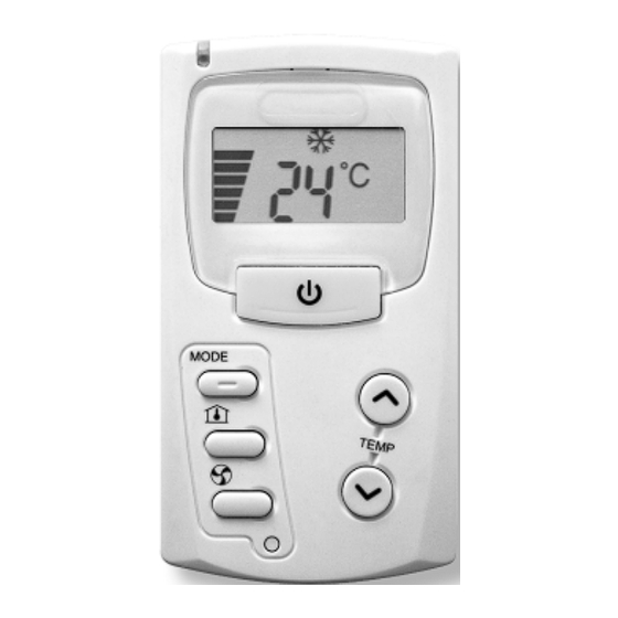
- Page 9 5 - RCL control installation STEP 1 STEP 3 Unscrew the lower screw on Make the electrical connections the RCL control. between the support bracket terminals and the FCC controller, Separate the RCL control and terminal 1 of the blue from its support bracket with connector to the terminal the help of a flat bladed...
- Page 10 6 - Commissioning Synchronising the units under master / slave control from an RCL control This operation must be performed if the RCL control or the FCC controller has been replaced, or in the case where one or several fan coil units have been electrically isolated. 1 -Synchronisation operations description 2-3 Press the ON / OFF key.
-
Page 11: General Wiring Diagrams
7 - General wiring diagrams... - Page 12 7 - General wiring diagrams (contd.)
- Page 13 7 - General wiring diagrams (contd.)
- Page 14 7 - General wiring diagrams (contd.)
- Page 15 7 - General wiring diagrams (contd.)
- Page 16 7 - General wiring diagrams (contd.) Aqu@Net System E 4 PIPE VALVE action + VENTILATION POWER SUPPLY 230V/1Ph/50Hz Ground to the casing EH2 N BLUE CHESTNUT BROWN BLUE WHITE TERMINAL BLOCK REF 228 CHESTNUT BROWN RED LS VIOLET MS BLACK HS UNOC ALARM Aqu@Net...
-
Page 17: Ce Compliance Declaration
CE Compliance Declaration Under our own responsability, we declare that the product designated below complies with the provisions of the EEC directives listed hereafter and with the national legislation into which these directives have been transposed : Low Voltage Directive 73 / 23 / EEC Electro-magnetic Compatibility Directive 89 / 336 / EEC and that the following paragraphs of the harmonised standards have been applied : Déclaration CE de conformité... - Page 18 As part of our ongoing product improvement programme, our products are subject to change without prior notice. Non contractual photos. Dans un souci d'amélioration constante, nos produits peuvent être modifiés sans préavis. Photos non contractuelles. Wesper S.A. 42 cours Jean Jaurès...
Need help?
Do you have a question about the Aquanet and is the answer not in the manual?
Questions and answers