Table of Contents
Advertisement
Quick Links
The Tek-ENTRY
Apartment Entry Intercoms provide
Application
®
two-way communications between the building entrance
and each suite. Hands-free loudspeaker operation at
the entrance/lobby panel and push button controlled
communication at the suite/apartment locations provide
for easy operation. Controlled door entry is permitted by
push button operation at the suite in conjunction with
electric door release.
Optional equipment is available to provide additional
functionality, such as post office key door release,
additional entrance panels, strobe light call indication
(LI404B) and auxiliary relay (RY014B) for ancillary device
operation (bells, lights, etc.).
1. Read installation instructions to determine equipment
Procedure
location and installation methods.
2. Install housings (or back boxes) and wiring.
3. Check wiring, connect and install equipment.
4. Apply power and check operation.
Equipment Location
Locate suite stations (also known as remote stations)
Suite/Apartment Stations
where convenient for use. Install a housing or back box
at the desired location.
Use an OH190 series housing and OF190 series frame
Entrance/Lobby Panel
for flush wall mounting. Use an OF190S series frame for
surface mounting. Locate the entrance panel where it
is sheltered from weather.
Install the amplifier inside the entrance panel when
PK543A Amplifier
using an OH190 series housing. The amplifier must
be installed outside the entrance panel when using
an OF190S series surface frame. Refer to
section, item #3, on page 2
Phone: 828.524.9967 • Fax: 828.524.9968 • Sales: Choose option 2 • Tech Support: Choose option 3
TekTone's quality system is registered by DQS to the ISO 9001 standard. (Reference #10001510.)
for further details.
Connections
www.tektone.com
324 Industrial Park Road • Franklin, NC 28734 •
IL826 Installation Instructions and Wiring
Tek-ENTRY
Apartment Entrance Panels • Rev. 7 – 11/2016
®
Stations may be connected in risers using the following
Suite/Apartment Stations
cable configurations:
3-wire stations: 1 twisted pair #22 AWG, plus 1
conductor #22 AWG per station in riser.
4-wire stations: 1 twisted pair #22 AWG, plus 1
conductor #22AWG, plus 1 conductor #22 AWG per
station in riser.
5-wire stations: 1 twisted pair #22 AWG, plus 2
conductor #22 AWG, plus 1 conductor #22 AWG per
station in riser.
The maximum cable length is 400 feet (120 meters).
Additional risers may be added as needed. Station cables
must not be run in the same conduit with (or too close
to) electrical wiring or background music, and must
not be close to fluorescent lighting or other electrical
equipment. Failing to observe this requirement can
result in noise entering the intercom audio. Ensure that
sufficient amounts of cable are left in the back box to
make connections to stations.
Cable wiring must be 2 conductor #18 AWG with a
Transformer
maximum cable length of 80 feet (25 meters). If using
#14 AWG wire, this distance can be extended to 200
feet (60 meters). Route cable away from suite station
wiring and maintain a minimum of 3 feet (1 meter) of
clearance between the transformer and the amplifier.
Cable wiring must be 2 conductor #18 AWG with a
Door Release
maximum length of 50 feet (15 meters). See
for specifics of each door control unit
configuration. Note: An SS106 transformer must be
on page 5
used for 24 VAC doorstrike and 12 VDC Maglock
applications (8 volt tap required).
tektone@tektone.net
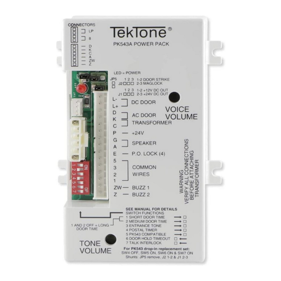
PK543A Amplifier
Wiring
Figure 2
Advertisement
Table of Contents

Summary of Contents for TekTone PK543A
- Page 1 324 Industrial Park Road • Franklin, NC 28734 • tektone@tektone.net Phone: 828.524.9967 • Fax: 828.524.9968 • Sales: Choose option 2 • Tech Support: Choose option 3 TekTone’s quality system is registered by DQS to the ISO 9001 standard. (Reference #10001510.)
-
Page 2: Optional Accessories
Set SW3 to ON (right) to activate this feature—must use warble tone Entrance Tone Page 2 • IL826 PK543A Installation Instructions and Wiring Copyright © TekTone Sound & Signal Mfg., Inc. All Rights Reserved. -
Page 3: Talk Button
Talk Button the suite station’s internal speaker to terminals 1 and 2 of the PK543A, which serves as an audio input to talk Check wiring to door release for shorts and opens, the amplifier. The audio is then amplified and sent to No Door Operation or for defective door release. - Page 4 Page 4 • IL826 PK543A Installation Instructions and Wiring Copyright © TekTone Sound & Signal Mfg., Inc. All Rights Reserved.
- Page 5 #18 AWG Wire Note: LP and 8 are each available on two pins of the JP3 connector. Brackets are provided to identify. IL826 PK543A Installation Instructions and Wiring • Page 5 Copyright © TekTone Sound & Signal Mfg., Inc. All Rights Reserved.
- Page 6 Page 6 • IL826 PK543A Installation Instructions and Wiring Copyright © TekTone Sound & Signal Mfg., Inc. All Rights Reserved.
-
Page 7: Power Led
Also remove JP5 shunt, set J2 to shunt 1 - 2 and set J1 shunt to 2 - 3. IL826 PK543A Shunts and Settings RY014B Wiring Rev4 091913 IL826 PK543A Installation Instructions and Wiring • Page 7 Copyright © TekTone Sound & Signal Mfg., Inc. All Rights Reserved. - Page 8 Page 8 • IL826 PK543A Installation Instructions and Wiring Copyright © TekTone Sound & Signal Mfg., Inc. All Rights Reserved.
Need help?
Do you have a question about the PK543A and is the answer not in the manual?
Questions and answers