Table of Contents
Advertisement
Technical Reference Guide
Product Overview
Describes features for this product.
Setup
Describes how to install and set this product.
Handling
Describes the basic usage of this product.
Application Development Information
Describes how to control this product and information
necessary for developing applications.
Appendix
Describes the specifications and character code tables.
M00093701
Rev. B
Advertisement
Table of Contents

Related Manuals for Epson DM-D30


Summary of Contents for Epson DM-D30
-
Page 1: Product Overview
Technical Reference Guide Product Overview Describes features for this product. Setup Describes how to install and set this product. Handling Describes the basic usage of this product. Application Development Information Describes how to control this product and information necessary for developing applications. Appendix Describes the specifications and character code tables. - Page 2 Neither is any liability assumed for damages resulting from the use of the information contained herein. Neither Seiko Epson Corporation nor its affiliates shall be liable to the purchaser of this product or third par- ties for damages, losses, costs, or expenses incurred by the purchaser or third parties as a result of: accident, misuse, or abuse of this product or unauthorized modifications, repairs, or alterations to this product, or (excluding the U.S.) failure to strictly comply with Seiko Epson Corporation’s operating and maintenance...
-
Page 3: For Safety
Do not allow foreign matter to fall into the equipment. Penetration by foreign objects may lead to fire. If water or other liquid spills into this equipment, disconnect the USB cable immediately, and then contact your dealer or a Seiko Epson service center for advice. Continued usage may lead to fire. -
Page 4: Cautions
Cautions Do not connect cables and external interfaces in ways other than those mentioned in the man- ual. Different connections may cause equipment damage and burning. Be sure to set this equipment on a firm, stable, horizontal surface. The product may break or CAUTION cause injury if it falls. -
Page 5: Restriction Of Use
Aim of the Manual This manual provides the development engineers with necessary information for developing, designing, install- ing the system using DM-D30 as well as for developing and designing the applications. Manual Content The manual is made up of the following sections:... -
Page 7: Table Of Contents
Contents ■ For Safety..........................3 Key to Symbols..................................3 Warnings ....................................3 Cautions....................................4 ■ Restriction of Use ........................5 ■ About this Manual ........................5 Aim of the Manual ................................5 Manual Content .................................. 5 ■ Contents............................7 Product Overview ..................11 ■ Features ..........................11 ■... - Page 8 Application Development Information ............25 ■ Controlling the Customer display ..................25 ePOS-Print XML ................................25 ESC/POS ....................................25 ■ Software..........................26 Development Kits................................26 Drivers....................................26 Manuals....................................27 Download................................... 27 Appendix ......................29 ■ Product Specifications ......................29 Environmental Conditions ............................29 External Dimensions and Mass...........................
- Page 9 Page 45 (WPC1250: Latin 2)............................62 Page 46 (WPC1251: Cyrillic)............................63 Page 47 (WPC1253: Greek) ............................64 Page 48 (WPC1254: Turkish)............................65 Page 49 (WPC1255: Hebrew) ............................66 Page 50 (WPC1256: Arabic) ............................67 Page 51 (WPC1257: Baltic Rim) ...........................68 Page 52 (WPC1258: Vietnamese)..........................69 Page 53 (KZ1048: Kazakhstan) ............................70 Page 254 (User-Defined Page).............................71 Page 255 (User-Defined Page).............................72 International Character Sets............................73...
-
Page 11: Product Overview
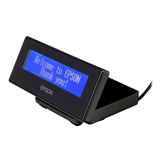
Product Overview This chapter describes features of the product. Features DM-D30 is a customer display for displaying characters. The main features of this product are as follows. Display 20 digit x 2 lines dot matrix for displaying half-width characters. -
Page 12: Part Names And Functions
Part Names and Functions Contrast adjustment control Move this to adjust the contrast of the LCD screen. Display Displays on the LCD screen. You can adjust the angle of the display. Note: The display is covered with a protective film. Remove before use. Stand Supports the display unit. -
Page 13: System Outline
This section explains the system connection pattern using this product. Connecting with TM-m30 Connect this product’s USB cable to the TM-m30. Power is supplied from the TM-m30. TM-m30 DM-D30 Connecting with Computer Connect this product’s USB cable to the computer. Power is supplied from the computer. Computer DM-D30 ... -
Page 15: Setup
Chapter 2 Setup Setup This chapter explains the installation and setting operations necessary to use this product. Connecting to the Printer Connect the USB cable of the customer display to the USB connector on the printer. When you connect the USB cable to the printer, be sure to turn off the printer before connect- ing. -
Page 16: Connecting To The Computer
Connecting to the Computer Connect the USB cable of the customer display to the USB connector on the computer. We do not recommend using this USB bus power device with a USB extension cable. Depending on the configuration of the cable, operational errors or a deterioration in EMC characteristics may occur due to a drop in voltage. -
Page 17: Connecting The Printer's Wireless Lan Unit
Chapter 2 Setup Connecting the Printer’s Wireless LAN Unit When the Wireless LAN unit is connected to the printer's USB connector and there are no free USB connectors, you can use the Wireless LAN unit and the customer display at the same time by connecting the Wireless LAN unit to the Wireless LAN unit connector on this device. - Page 18 Connect the Wireless LAN unit to the Wireless LAN unit connector. Reattach the cover for the bottom. Keep the cover for the stand removed. Do not place anything in the upper section (cover opening) of the Wireless LAN unit. If heat is not allowed to dissipate when using the product, it may lead to a malfunction.
-
Page 19: Drawing Out The Cable
Chapter 2 Setup Drawing Out the Cable You can draw out the USB cable from the front, the side, or the back. Be sure to turn off the power on the printer when connecting USB cable to the printer. -
Page 20: Affixing The Customer Display
If you draw the cable from the front, fold the cable back inside the hollow of the stand, and then secure the cable as shown in the illustration, so that it does not become loose. Affixing the Customer Display You can use the affixing tape supplied to secure the device. Attach the affixing tape to the points shown in the following illustration. -
Page 21: Memory Switch Setting
Chapter 2 Setup Memory Switch Setting This product comes with memory switches as part of the software's setting features. These allow you to make settings for the TM-m30 Utility. For details, see the TM-m30 Utility User's Manual. Turn Off Backlight Select from 0 to 120 seconds Initial setting: Normally On Code-page... -
Page 23: Handling
Chapter 3 Handling Handling This chapter explains the basic handling methods for this product. Turning the Power On/Off The power for this product is supplied by USB bus power, which means that the power is supplied from the con- nected printer or computer through the USB connector. To turn this product on or off, turn the connected printer or computer on or off. -
Page 24: Cleaning The Outer Case
Cleaning the Outer Case Be sure to disconnect the USB cable from the printer or the computer, and then wipe the dirt off the outer case with a dry cloth or a damp cloth. Never clean the product with alcohol, benzine, thinner, or other such solvents. Doing so may damage or break the parts made of plastic and rubber. -
Page 25: Application Development Information
EPSON Advanced Printer Driver Ver.5 (APD5) ePOS-Print XML ePOS-Print XML is Epson's control command system for the customer display defined in XML. You can print from the socket communication environment or OS applications. For details of ePOS-Print XML, see the ePOS-Print XML User’s Manual. -
Page 26: Software
Development kits are only supported when connecting through the TM-m30. Drivers Operating Software Description environment EPSON Advanced Printer Driver Windows printer driver that can display on the customer dis- Windows Ver.5 (APD5) play. You cannot send ESC/POS commands to the customer dis- play or monitor the status. -
Page 27: Manuals
You can obtain software and manuals from one of the following URLs. For customers in North America, go to the following web site and follow the on-screen instructions. http://www.epsonexpert.com/ For customers in other countries, go to the following web site: http://download.epson-biz.com/?service=pos... -
Page 29: Appendix
Appendix Appendix Product Specifications Display type STN LCD (160 x 32 dots) Number of characters displayed 40 characters (20 columns x 2 rows) Display color White/Blue Brightness 100 cd/m2 Character classes Alphanumeric: 95 characters (8 x 16 dots) International characters: 18 sets (8 x 16 dots) Graphic characters: 128 characters x 41 pages Character size 4.1 x 8.3 mm {0.16 x 0.33"} (W x H, alphanumeric) -
Page 30: External Dimensions And Mass
External Dimensions and Mass Item Specification Width 130 mm (5.12 inches) Depth 100 mm (3.94 inches) Height 68 mm (2.68 inches) Mass 0.3 kg When the angle of display unit is 0 degree. [Unit: mm]... -
Page 31: Character Code Tables
Appendix Character Code Tables The character code tables show only character configurations. They do not show the actual print pattern. “SP” in the table shows a space. Common to All Pages When the international character set (See "International Character Sets" on page 73.) is USA:... -
Page 32: Pc437: Usa, Standard Europe]
Page 0 [PC437: USA, Standard Europe]... -
Page 33: Katakana)
Appendix Page 1 (Katakana) -
Page 34: Pc850: Multilingual)
Page 2 (PC850: Multilingual) -
Page 35: Pc860: Portuguese)
Appendix Page 3 (PC860: Portuguese) -
Page 36: Pc863: Canadian-French)
Page 4 (PC863: Canadian-French) -
Page 37: Pc865: Nordic)
Appendix Page 5 (PC865: Nordic) -
Page 38: Pc851: Greek)
Page 11 (PC851: Greek) -
Page 39: Pc853: Turkish)
Appendix Page 12 (PC853: Turkish) -
Page 40: Pc857: Turkish)
Page 13 (PC857: Turkish) -
Page 41: Pc737: Greek)
Appendix Page 14 (PC737: Greek) -
Page 42: Iso8859-7: Greek)
Page 15 (ISO8859-7: Greek) -
Page 43: Wpc1252)
Appendix Page 16 (WPC1252) -
Page 44: Pc866: Cyrillic #2)
Page 17 (PC866: Cyrillic #2) -
Page 45: Pc852: Latin 2)
Appendix Page 18 (PC852: Latin 2) -
Page 46: Pc858: Euro)
Page 19 (PC858: Euro) -
Page 47: Tcvn-3: Vietnamese)
Appendix Page 30 (TCVN-3: Vietnamese) -
Page 48: Tcvn-3: Vietnamese)
Page 31 (TCVN-3: Vietnamese) -
Page 49: Pc720: Arabic)
Appendix Page 32 (PC720: Arabic) -
Page 50: Wpc775: Baltic Rim)
Page 33 (WPC775: Baltic Rim) -
Page 51: Pc855: Cyrillic)
Appendix Page 34 (PC855: Cyrillic) -
Page 52: Pc861: Icelandic)
Page 35 (PC861: Icelandic) -
Page 53: Pc862: Hebrew)
Appendix Page 36 (PC862: Hebrew) -
Page 54: Pc864: Arabic)
Page 37 (PC864: Arabic) -
Page 55: Pc869: Greek)
Appendix Page 38 (PC869: Greek) -
Page 56: Iso8859-2: Latin 2)
Page 39 (ISO8859-2: Latin 2) -
Page 57: Iso8859-15: Latin 9)
Appendix Page 40 (ISO8859-15: Latin 9) -
Page 58: Pc1098: Farsi)
Page 41 (PC1098: Farsi) -
Page 59: Pc1118: Lithuanian)
Appendix Page 42 (PC1118: Lithuanian) -
Page 60: Pc1119: Lithuanian)
Page 43 (PC1119: Lithuanian) -
Page 61: Pc1125: Ukrainian)
Appendix Page 44 (PC1125: Ukrainian) -
Page 62: Wpc1250: Latin 2)
Page 45 (WPC1250: Latin 2) -
Page 63: Wpc1251: Cyrillic)
Appendix Page 46 (WPC1251: Cyrillic) -
Page 64: Wpc1253: Greek)
Page 47 (WPC1253: Greek) -
Page 65: Wpc1254: Turkish)
Appendix Page 48 (WPC1254: Turkish) -
Page 66: Wpc1255: Hebrew)
Page 49 (WPC1255: Hebrew) -
Page 67: Wpc1256: Arabic)
Appendix Page 50 (WPC1256: Arabic) -
Page 68: Wpc1257: Baltic Rim)
Page 51 (WPC1257: Baltic Rim) -
Page 69: Wpc1258: Vietnamese)
Appendix Page 52 (WPC1258: Vietnamese) -
Page 70: Kz1048: Kazakhstan)
Page 53 (KZ1048: Kazakhstan) -
Page 71: User-Defined Page)
Appendix Page 254 (User-Defined Page) -
Page 72: User-Defined Page)
Page 255 (User-Defined Page) -
Page 73: International Character Sets
Appendix International Character Sets...
Need help?
Do you have a question about the DM-D30 and is the answer not in the manual?
Questions and answers