Table of Contents
Advertisement
Quick Links
Advertisement
Table of Contents

Summary of Contents for Knick VariTrans P 2900x P2
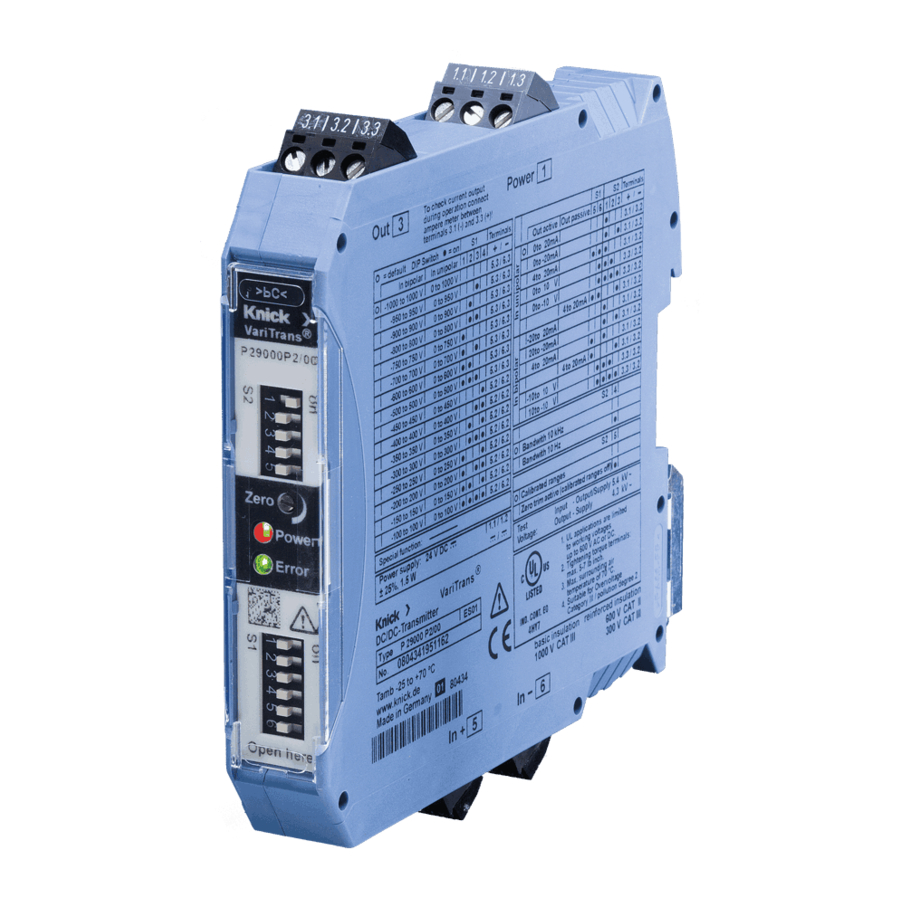
- Page 1 VariTrans® P 2900x P2 High-Voltage Isolation Amplifiers www.knick.de...
-
Page 2: Warranty
Warranty Warranty Defects occurring within 5 years from delivery date shall be remedied free of charge at our plant (carriage and insurance paid by sender). Accessories: 1 year. Subject to change without notice. Return of products Please contact our Service Team before returning a defective device (see back cover for contact details). -
Page 3: Table Of Contents
Table of Contents Warranty ..................32 Safety Information ...............34 Intended Use .................35 Function ..................36 Mounting and Electrical Connection ........37 Control Elements (Face Plate) ............38 Status Signaling ................38 Test Jacks ..................39 Input Ranges .................40 Output Ranges ................42 Typical Input Configurations ............43 Typical Output Configurations ..........44 Characteristic Curves ..............46 Specifications ................48 Input data .....................48... -
Page 4: Safety Information
Safety Information Warning! Protection against electric shock For applications with high working voltages, ensure there is suffi cient spacing or isolation from neighboring devices and protection against electric shocks. Caution! Be sure to take protective measures against electrostatic discharge (ESD) when handling the devices! Caution! The VariTrans®... -
Page 5: Intended Use
Intended Use The VariTrans® P2900xP2 high-voltage isolation amplifi ers are designed for input voltages up to 1000 V DC. The calibrated range selection is performed using DIP switches. The input signal is reproduced as a 0/4 … 20 mA or 0 … 10 V standard signal or as a bipolar signal in the –20 ... 20 mA or –10 ... 10 V range at the output. -
Page 6: Function
Function The input signal is converted into a pulse-width modulated signal and is transferred to the primary side of a transformer. On the second- ary side the pulse-width signal is converted back into an impressed current or an impressed voltage. 3-port isolation with protective separation up to 600 V AC/DC according to EN 61140 ensures optimum protection of personnel and equipment as well as unaltered transmission of measuring signals. -
Page 7: Mounting And Electrical Connection
Mounting and Electrical Connection The devices are snapped onto TS 35 standard rails and laterally fi xed by suitable end brackets. See dimension drawing for terminal assignments. Conductor cross-section: 0.2 mm ... 2.5 mm (AWG 24-12). Terminal assignments and dimensions 17,5 99,0 3.3 3.2 3.1... -
Page 8: Control Elements (Face Plate)
Control Elements (Face Plate) Switch S1 Function (factory setting bold print) Input range Output range Switch S2 Output, active Output, passive Voltage output Current output Output inverted Output not inverted Cutoff frequency 10 Hz Cutoff frequency 10 kHz Off set pot active Calibrated range Switch S2 Potentiometer (output offset, max. -
Page 9: Test Jacks
Test Jacks Warning! Protection against electric shock For applications with high working voltages, ensure there is suffi cient spacing or isolation from neighboring devices and protection against electric shocks. Be sure to use suitable high-voltage test prods with suffi cient protection against shock hazards! The VariTrans®... -
Page 10: Input Ranges
Input Ranges Input ranges P 29000 P2/0x (Factory setting: Range 1) No. Input range Switch Input Input resistance terminals Bipolar Unipolar... - Page 11 Input Ranges Input ranges P 29001 P2/0x (Factory setting: Range 1) No. Input range Switch Input Input resistance terminals Bipolar Unipolar...
-
Page 12: Output Ranges
Output Ranges Output ranges P 2900x P2/0x (Factory setting: Range 1) No. Input Output, Output, Output active passive 5 ... 6 1 ... 3 terminals Unipolar Unipolar Unipolar Unipolar Unipolar Unipolar Bipolar Bipolar Bipolar 10 Bipolar 11 Bipolar 12 Bipolar... -
Page 13: Typical Input Configurations
Typical Input Configurations Voltage measurement Voltage measurement Shunt voltage measurement... -
Page 14: Typical Output Configurations
Typical Output Configurations Current output, active The voltage measurement shown here serves for load control Voltage output Legend Test jack Terminal Optional voltage measurement Optional current measurement (only DC currents can be measured correctly) - Page 15 Typical Output Confi gurations The device is confi gured for “Passive output” (unipolar/bipolar): S2-1 V Behavior with missing power supply output The externally controlled output current rises to approx. 57 mA, 14 V the red LED is glowing slightly. 24 V The externally controlled output current rises to approx.
-
Page 16: Characteristic Curves
Characteristic Curves Transfer characteristic with indication of the adjustable off set. Up to 105% input span the amplifi er operates linearly with full accuracy. Transfer characteristic with adjustable RangeLimit (min, special version) and adjustable off set... - Page 17 Characteristic Curves Inverting transfer characteristic with adjustable RangeLimit (max, special version) and adjustable off set Built-in full-wave rectifi er with absolute-value function (V-shape curve, special version) and adjustable off set...
-
Page 18: Specifications
Specifications Input data (voltage) Input range max. ±1000 V DC Overload capacity 0 ... 1 V max. ± 30 V (permanent) 1 ... 100 V max. ± 500 V 100 ... 500 V max. ± 600 V 500 ... 1000 V max. -
Page 19: Output Data
Specifi cations Output data Output, active 0/4 … 20 mA or 0 … 10 V, resp., or –20 … 20 mA or –10 … 10 V, resp. Output, passive 4 … 20 mA Max. load (current) active ≤ 12 V (600 Ω at 20 mA) passive 12 ... -
Page 20: Power Supply
Specifi cations Common mode rejection CMRR appr. 150 dB (DC/AC: 50 Hz) Input range ≤ 1 V T-CMRR appr. 100 dB (1000 V, t = 1 μs) Common mode rejection CMRR DC: approx. 150 dB Input range > 1 V AC 50 Hz: approx. -
Page 21: Isolation
Specifi cations Isolation Galvanic isolation 3-port isolation between input, output and power supply Test voltage 5.4 kV AC input against output and power supply 4.3 kV AC power supply against output Working voltage Up to 1000 V AC/DC across all circuits (basic insulation) with overvoltage category III and pollution degree 2. -
Page 22: Standards And Approvals
Specifi cations Protection against Protective separation to EN 61140 electric shock by reinforced insulation according to EN 61010-1. Working voltage up to 600 V AC/DC across all circuits with overvoltage category II and pollution degree 2. For applications with high working volt- ages, ensure there is suffi cient spacing or isolation from neighboring devices and protection against electric shocks. -
Page 23: Further Data
Specifi cations Further data Ambient temperature Operation: –25 ... +70 °C (min. start temp.: –40 °C) Operation with passive output: –25 ... +60 °C Transport and storage: –40 ... +85 °C Design Modular housing with screw terminals Housing width 17.5 mm Installation position Vertical or horizontal Diameter of test jacks... -
Page 24: Product Line
Product Line Product line Order no. P29000P2 / 0 _ - _ _ _ _ 24 V DC power supply Standard device VariPower® broad-range Standard device power supply (20 ... 230 V AC/DC) Version to customer requirements n n n n P29001P2 / 0 _ - _ _ _ _ 24 V DC power supply... -
Page 25: Accessories
Accessories Order No. IsoPower® A 20900 power supply 24 V DC, 1 A A 20900 H4 A 20900 H4 power supply DIN rail bus connector: Tapping of supply voltage ZU 0678 from A 20900 H4 (2 units required) Power terminal block, for connecting the supply ZU 0677 voltage to the ZU 0678 DIN-rail bus connector Required when more than 5 P 2900xP0 amplifi ers... - Page 26 Accessories P 2900xP0 ZU 0678 DIN rail bus connector IsoPower® A 20900 power supply A 20900 H4 P 2900xP0 ZU 0678 DIN rail bus connector ZU 0677 power terminal block...
Need help?
Do you have a question about the VariTrans P 2900x P2 and is the answer not in the manual?
Questions and answers