Advertisement
Table of Contents
- 1 Table of Contents
- 2 Specifications and Performance Data Sheet
- 3 Suggested Installation Equipment
- 4 Overview of the Economy RO System's Components (Line Pressure Model)
- 5 Overview of the Economy RO System's Components (Booster Pump Model)
- 6 Package Contents
- 7 Product Information
- 8 Preparations
- 9 Installation
- 10 Start-Up
- 11 Service and Maintenance
- 12 Parts Breakdown
- 13 Troubleshooting Guide
- 14 Warranty
- Download this manual
Economy RO
Installation, Operation & Service Instructions with Parts List
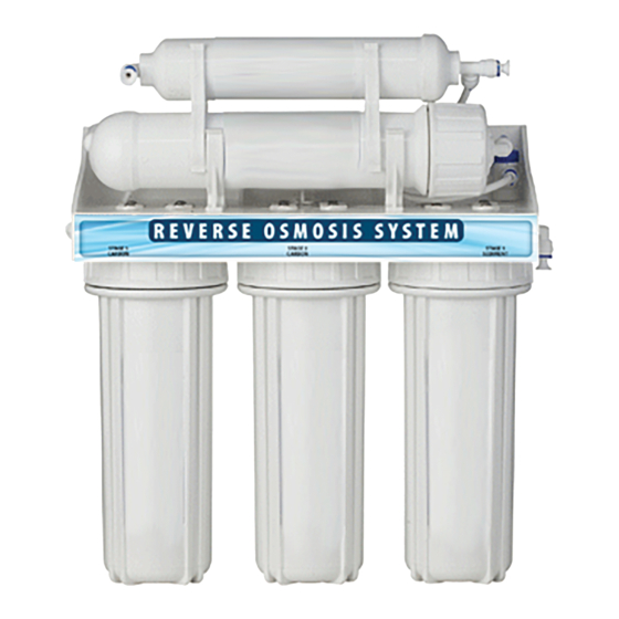
Economy Reverse Osmosis Drinking Water System
Models: RO75, RO75BP
Canada West
855 Park St., Unit 1
7503 35th St. SE
Regina, SK S4N 6M1
Calgary, AB T2C 1V3
Canada East
U.S.A.
490 Pinebush Rd., Unit 1
7229 University Ave NE
Cambridge, ON N1T 0A5
Fridley, MN 55432
56 Lightcap Rd.
Pottstown, PA 19464
9760 Mayflower Park Drive,
4655 McDowell Rd. W
Suite 110
Phoenix, AZ 85035
Carmel, IN 46032
Advertisement
Table of Contents

Summary of Contents for Reverse Osmosis Economy RO75
- Page 1 Economy RO Installation, Operation & Service Instructions with Parts List Economy Reverse Osmosis Drinking Water System Models: RO75, RO75BP Canada West Canada East U.S.A. 855 Park St., Unit 1 7503 35th St. SE 490 Pinebush Rd., Unit 1 7229 University Ave NE 9760 Mayflower Park Drive, 4655 McDowell Rd.
- Page 2 The Economy RO Drinking Water System contains a replaceable reverse osmosis membrane filter which is critical for the effective reduction of Total Dissolved Solids. The filtered water should be tested periodically to verify that the system is performing properly.
-
Page 3: Table Of Contents
Installation, Operation & Service Instructions with Part List Economy Reverse Osmosis Drinking Water System Table of Contents Page Specifications and Performance Data Sheet ..............2 Suggested Installation Equipment . -
Page 4: Specifications And Performance Data Sheet
Average Reduction**** % Typical System Flow Sequence Sediment Filter Activated Carbon Prefilter Activated Carbon Prefilter Reverse Osmosis Membrane Storage Tank Activated Carbon Postfilter Dispensing Faucet Sediment Filter (Stage 1).. -
Page 5: Suggested Installation Equipment
Temperature 40 - 77 ºF 2. The reverse osmosis membrane used in these systems may be Total Dissolved Solids (TDS) 1 damaged by chlorine. These systems include activated carbon filters 0 - 2500 ppm (0 - 2500 mg/L) which protect the membranes by reducing chlorine. -
Page 6: Overview Of The Economy Ro System's Components (Line Pressure Model)
RO membrane filter. It must be regularly checked and/or replaced to prevent premature membrane failure and poor water quality. Reverse Osmosis Membrane The RO membrane (4) reduces dissolved substances and other microscopic impurities. It consists of a membrane envelope wound around a perforated tube. -
Page 7: Overview Of The Economy Ro System's Components (Booster Pump Model)
RO membrane filter. It must be regularly checked and/or replaced to prevent premature membrane failure and poor water quality. Reverse Osmosis Membrane The RO membrane (4) reduces dissolved substances and other microscopic impurities. It consists of a membrane envelope wound around a perforated tube. -
Page 8: Package Contents
Package Contents Figure 3 1. RO Manifold with Flow Control 7. Drain Saddle (1/4” or 3/8”) 13. Transformer (for Booster pump model only) 2. Sediment Filter 8. Tank Shut-off Valve 14. Wrenches 3. Carbon Block Filter 9. Inlet 3-Way Valve 15. -
Page 9: Product Information
Product Information This manual covers the technical aspects of the Economy RO drinking water systems. It is important to read this manual thoroughly so that you can properly apply, install, and service these systems. The substances reduced by this system are not necessarily in the customer’s untreated water. Warranty A limited warranty is extended to the original end user from Canature WaterGroup. - Page 10 Storage Tank Preparation NOTE: Changing the air pressure will alter the amount of water stored in the tank. Increasing the pressure will decrease capacity while decreasing pressure will increase capacity. Plastic Tank WARNING! Do not use the tank ball valve to lift or carry the tank.
-
Page 11: Installation
Installation: RO75BP Unit The exact placement of the components will vary by installation. Although shown beneath a sink, it may be installed in a basement, crawl space, or in an adjacent cabinet. Regardless of where the system is installed, the flow sequence described by (figure 7) must be observed. - Page 12 Installation: RO75BP Unit The exact placement of the components will vary by installation. Although shown beneath a sink, it may be installed in a basement, crawl space, or in an adjacent cabinet. Regardless of where the system is installed, the flow sequence described by (figure 7) must be observed.
- Page 13 Installation: RO75 Unit The exact placement of the components will vary by installation. Although shown beneath a sink, it may be installed in a basement, crawl space, or in an adjacent cabinet. Regardless of where the system is installed, the flow sequence described by (figure 8) must be observed.
- Page 14 Installation: RO75 Unit The exact placement of the components will vary by installation. Although shown beneath a sink, it may be installed in a basement, crawl space, or in an adjacent cabinet. Regardless of where the system is installed, the flow sequence described by (figure 8) must be observed.
- Page 15 The following steps will enable you to install the system quickly and orderly. Some variation may be necessary depending on the installation. See page 4 for a check list of tools and materials. Typical installations follow this sequence: 1. Select Component Installation Locations 2.
- Page 16 Step 2 – Faucet Installation To simplify its access and installation, we suggest you install the faucet on the rear lip of the sink. It should be evenly positioned with the sink faucet and spray attachment. Should the spray faucet hole not be available for the installation, the sink must be drilled.
- Page 17 One proven tool is the Relton porcelain cutter kit when used with a slow speed drill (300-400 rpm). • Drill a pilot hole through the porcelain and base material with the carbide tip drill. • Build a putty dam around the drill area. Add enough water to lubricate cutters and reduce cutting noise. •...
- Page 18 Air Gap Faucet (Optional - Not Supplied With this Product) 3/8” White 1/4” White Tubing Tubing Faucet Base Rubber Washer (Remove white protective film.) Split Washer Lock Washer Spacer (Optional) Faucet Adapter Drain Line from Faucet (3/8”...
- Page 19 Non Air Gap Faucet (Supplied With the Product) Faucet Small Rubber Washer Base Large Rubber Washer (Remove white protective film) Lock Washer Plastic Washer Faucet Adapter Drinking Water Line to Faucet (3/8” Blue Tubing) Standard Faucet Installation 1.
- Page 20 Air Gap Faucet Installation Remove white protective film from faucet base. Verify faucet body, metal base, and rubber base washer are in place above sink (Items 1, 3, and 2). Lower faucet into mounting hole and place faucet over hole. Install slotted washer, spacer, faucet washer, and nut onto faucet nipple below sink and snug them up (Items 4, 5, 6, 7 and 8).
- Page 21 Step 4 – Connect System Drain Plumbing codes require that the drain from reverse osmosis drinking water systems be discharged through an air gap siphon break. The faucet incorporates an air gap into its body. The discharge from the air gap must be connected to the plumbing system for proper drainage.
- Page 22 Drain Saddle Figure 14 1. Install the drain saddle valve on to the 2. Tighten the clamps with the help of the drain pipe. See figure 7 on page 9 for its two bolts. location. For AirGap Faucet, Also install WARNING! Do not the elbow fitting provided with the drain overtighten.
- Page 23 Many homes are equipped with disposals and dishwashers. Special care must be taken when these appliances are present to prevent improper air gap performance. Home drain plumbing must be free of any blockage since this may cause a backup of dishwasher and disposal waste into the air gap outlet tube and result in improper air gap performance. To perform a simple drain check, fill the sink basin with several inches of water, pull the plug, and observe the drainage.
- Page 24 Top O Ring Bottom O Ring 3. Apply Lube to both O Rings 4. Pierce Plastic Wrap with scissors 5. Remove Plastic Wrap from Filter 6. Insert Filter into Sump 7. Attach Sump to Manifold 8. Tighten the Sump with Wrench Post Carbon Sediment...
- Page 25 15A. Insert RO Membrane as shown 15B. 16. Your system is ready to install. in 15B Install RO Manifold Under the Sink 1. Find a suitable place for manifold 2. Raise the manifold by 2 inches 3. Mark the holes with Pencil ... and check to make sure it fits 4.
- Page 26 Install Tank 1. Place Tank under the sink. The Shut off valve is already installed in the early steps Connect the Tubing (Non AirGap Version) Post Carbon Filter Flow Clip Control Plug Drain Saddle 1. Attach 1/4” Tubing to Flow 2.
- Page 27 Tubing Connections on Non Air Gap Faucet...
- Page 28 Tubing Connections on Air Gap Faucet Connections are same as on Non Air Gap Faucet, except for: 1. Drain Line from Faucet: Connects to Drain Saddle 2. Drain Line from Faucet: Connects to drain flow control in the RO manifold...
-
Page 29: Start-Up
Factors Which Affect Performance Performance of the reverse osmosis membrane is affected by several factors which must be considered when judging the condition of the system. The main factors which affect system performance are pressure, temperature, total dissolved solids level, recovery and pH. - Page 30 an iron filter. Clear water iron can be removed more effectively by a softener. Particulate iron can be removed more effectively by a 1 micron filter. Organic-bound iron can be removed only by activated carbon or macroporous anion resin. If there is enough iron to exceed the EPA secondary drinking water standard and softening the water is not an option and the iron is soluble, then an iron filter is appropriate.
-
Page 31: Service And Maintenance
• Stage 5 Carbon Block Post Filter • TDS of incoming and product water • Tank Pressure NOTE: The reverse osmosis membrane (Stage 4) Part is recommended to be changed once every three years or as needed. Metal Tank Sanitization Procedure Tank Pressure Check 1. - Page 32 3. Turn on the water and open the tank valve and close the faucet. When tank is full, open the faucet to flush the system Flush Valve The flush valve can be used periodically to flush the reverse osmosis membrane. All need to be done is to turn on the shut off valve shown and close it after 10 minutes.
-
Page 33: Parts Breakdown
Parts Breakdown: Line Pressure Part # Part Description 60095708 Shut-off Valve 60095701 300CC Flow Control 60095702 Flow Control QC 60095695 Post Carbon T-QC 92020 Post Carbon 60095697 Post Carbon QC Elbow 60095698 Clamp (RO--Post Carbon) 26196 10“ Carbon Cartridge 60095709 QC Elbow 60095682 Connector... - Page 34 Parts Breakdown: Booster Pump Part # Part Description Part # Part Description 92022 RO Membrane 26196 10“ Carbon Cartridge 60095695 Post Carbon T-QC 60095674 Cartridge T-QC 92020 Post Carbon 60095675 Pump QC Elbow 60095697 Post Carbon QC Elbow 60095676 Pump QC 60095698 Clamp (RO--Post Carbon) 60095677...
-
Page 35: Troubleshooting Guide
Troubleshooting Guide If a problem cannot be corrected through the use of this troubleshooting guide please have the following information ready prior to calling the 1-800 number on the back of this manual: • Serial # • Model # Problem Possible Cause Remedy Insufficient... - Page 36 Problem Possible Cause Remedy External leakage. a. Tubing not fully seated in fitting a. Check all fittings for tightness. b. Tubing abraded in seal area. b. Recut tubing and redo connection. Overflow at a. Concentrate tubing plugged. a. Clean concentrate tubing of debris. faucet air gap b.
-
Page 37: Warranty
Canature Watergroup Guarantee Subject to the conditions and limitations described below, Canature WaterGroup warrants its Economy Reverse Osmosis Drinking Water Treatment Systems (excluding membrane and cartridge filters), when installed in accordance with the specifications, to be free from defects in materials and workmanship under normal use within the operating specifications for a period of One (1) year from the date of purchase (with bill of sale). - Page 40 Canature WaterGroup™ 855 Park Street, Unit 1 Regina, SK. S4N 6M1 Canada Toll Free: (877) 288-9888 USA Office: 9760 Mayflower Park Drive, Suite 110 Carmel, IN. 46032 Toll Free: (877) 288-9888 55243.11/17...
Need help?
Do you have a question about the Economy RO75 and is the answer not in the manual?
Questions and answers