
Summary of Contents for Brahms B2
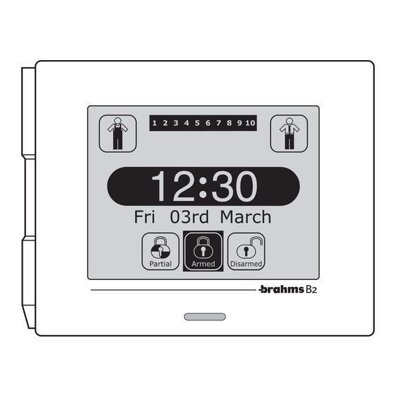
- Page 1 Burglar Alarm System 1 2 3 4 5 6 7 8 9 10 12 : 30 Fri 03rd March Partial Armed Disarmed Technical Manual 09-05-2011 - 24848602...
-
Page 3: Table Of Contents
CONTENTS 1- GENERAL SETTING State of the connected sensors ........28 INFORMATION Page 5 Erasing a device..............28 View Devices State ..............29 Introduction ................. 6 Setting Menu ................30 General Information on Setting Input Setting ................31 the Control Panel - B2UC0002 ......... 7 - Type of Input ................ -
Page 5: 1- General Setting Information
GENERAL SETTING INFORMATION... -
Page 6: Introduction
Introduction This section of the Installer Manual is NOT intended to define the operating procedures for setting the system parameters (covered in the next chapter), but has the purpose of providing basic information concerning the characteristics of the system. Reading this chapter is essential in order to understand the system's performance and be able to take full advan- tage of its capabilities. -
Page 7: General Information On Setting The Control Panel - B2Uc0002
General Information on Setting the Control Panel - B2UC0002 HOW TO ACCESS THE SETTING FUNCTIONS. 1 2 3 4 5 6 7 8 9 10 With the system turned off, i.e., with no area armed, press the icon (fig. 1). 12 : 30 Fri 03rd March Partial... - Page 8 In the Setting Menu, there are a series of icons that, when pressed, allow access to the setting Setting Menu parameters of: In In Out Out In In Inputs 0 123456789 0 123456789 0 123456789 0 123456789 Alarm Gen. Param. Out Out Outputs Users...
-
Page 9: Inputs Or Zones
In In Input Setting Inputs or Zones 4 IN Module 01.4 01 Area The definitions of the parameters for each burglar alarm input or zone is fundamental to the crea- Burglar Alarm tion of a safe, functional system. The following is a Entry Delay=000 description of some of the parameters that can be Exit Delay =000... -
Page 10: Areas
– The Installer (in agreement with the User) must A4 A3 decide the partial activation mode of the sys- tem: . Through free selection by the User of the areas to be activated . Through activation of sceneries predefi ned by A7 A8 the Installer during setting. - Page 11 emit a continuous buzzer sound to advise the user of “Generic Alarm” input the imminent activation of the alarm system. This type of input is intended to be associated with The “Entry Delay” and “Exit Delay” apply ONLY to inputs sensors or detectors for gas leaks, flooding, fire, etc.
-
Page 12: Type Of Balancing
Activates Activates Sound Activates Visual Activates Input/event type Activated if Sirens Signal (2) Signal (3) Outputs (4) Burglar Alarm Armed Area YES (1) YES – Intermittent Silent Alarm Always Rescue Alarm Always Panic Alarm Always YES (1) YES – Intermittent Tamper Alarm Always YES –... - Page 13 One Resistance Mode - Schematic diagram for the 'one resistance mode' connection of a device with Normally Closed alarm contact. Alarm Alarm Alarm Alarm contact contact contact contact Standby condition Alarm condition Line cut Short circuit on line input closed at earth open input open input alarm...
-
Page 14: Rolling Shutter Sensor
VIBRATION SENSOR This type of selection allows the direct connection This type of selection allows the direct connection (without requiring an interface card) to the Brahms (without requiring an interface card) to the Brahms CFSST prewired cable contact input modules for SVAMB and SINZI breaking sensor input modules. -
Page 15: Gong Option
GONG OPTION TAMPER An attribute which can be assigned to “Burglar This option allows the installer to choose whether Alarm” inputs with a type of balancing other than or not the B2MI0401 input modules should man- “Rolling Shutter Sensor” and “Vibration Sensor”. age the tamper signal separately from the alarm A “Gong”... -
Page 16: Outputs
Out Out Output Setting Outputs 2 OUT Module 01.2 9 10 For greater immediacy in the viewing of events, Areas Not Ready each output can be assigned an alphanumeric description of 14 characters. Pulse Normally Active ACTIVATING AREA For the outputs as well, it is also possible to select the group of areas for which these will be activated (fig. -
Page 17: Output Type
The table below provides the complete list of and their interaction with the areas. events that can be selected from the display (fig. 10) Conditioned Siren Activates Activates Events Activated if by the Areas Activation Sound Signal ⁽²⁾ Visual Signal ⁽³⁾ No events Always Accessories Aux PW Fault... -
Page 18: Users
User Setting Users Marco Each User can be assigned a group of areas and/or sceneries that will be the only ones the 9 10 User can arm and/or disarm (fi g. 12). It is also possible to assign each user a priority level from 1 to 4 , which will allow or not the user to perform a series of operations, as specifi ed in the... -
Page 19: Priority Levels
PRIORITY LEVELS User with priority level 4 - Can be considered the system administrator because he has access to all the functions that can be managed by the User. User with priority level 3 - Is the normal user of the system that can arm and disarm the system but does not require access to particular functions. -
Page 21: Setting The Control Panel
SETTING THE CONTROL PANEL... -
Page 22: Main Window With The System Turned Off
Main window with the system turned off Installer Menu access State of Areas display All areas deactivated 1 2 3 4 5 6 7 8 9 10 All areas activated 1 2 3 4 5 6 7 8 9 10 Areas partially activated 3 4 5 9 10... - Page 23 With the system turned off , i.e., with no area armed, press the icon (fi g. 1). 1 2 3 4 5 6 7 8 9 10 A keypad will appear on which to enter the Installer Code (which at the fi rst start-up will be 5, 6, 7, 8, fi g. 12 : 30 2) in order to access the Installer Menu (fi g.
-
Page 24: Learning
Devices Detected Learning Learn Start devices detection? When the appropriate icon is pressed, the system automatically detects the connected devices (fig. At this point, a list will appear with the number of devices detected and a different icon for each type of device (fig. -
Page 25: Identification
I I I Devices Detection Devices Detection 4 IN Module Power Supplier I I I Identification Mod 4 IN 01.1 PW. OUT 01.1 Identify Mod 4 IN 01.2 PW. OUT 01.2 Mod 4 IN 01.3 PW. OUT 01.3 Mod 4 IN 01.4 PW. -
Page 26: Assigning A Symbolic Name To The Devices
Consider a 4-input module as an example; the first line (fig. 9) cannot be changed, it contains the Devices Detection default name assigned by the system and represents 4 IN Module the type of device recognized. Mod 4 IN 01.1 Mod 4 IN 01.2 Mod 4 IN 01.3 Mod 4 IN 01.4... -
Page 27: Check Module Operation
CHECK MODULE OPERATION We will now consider as an example another device Devices Detection recognized by the system during detection, and Sensore IR Par. we will analyze the column indicated by the arrow Wall IR 01.1 (fig. 12). Clicking on this icon, we act on the state of the device as follows: Included ID: 022228632 V:0.1... -
Page 28: State Of The Connected Sensors
STATE OF THE CONNECTED SENSORS If there are inputs in alarm even though there are Devices Detection no activating events in progress, then it is neces- 4 IN Module sary to check the correctness of the connection Mod 4 IN 01.1 and its consistency with the setting of the “type of Mod 4 IN 01.2 balancing”... -
Page 29: View Devices State
S S S Installer Menu S S S View Devices State View I I I S S S P P P I I I S S S P P P Learn View Identify Setting By pressing the appropriate icon (fig. 16), it is pos- 1 2 3 sible to check the state of the connected devices;... -
Page 30: Setting Menu
P P P Installer Menu P P P Setting Menu Setting I I I S S S P P P I I I S S S P P P From the “Installer Menu”, pressing the appropriate Learn View Identify Setting 1 2 3 icon (fi g. -
Page 31: Input Setting
In In Input Setting INPUT SETTING 4 IN Module 01.4 01 Area For greater immediacy in the viewing of events, Burglar Alarm each input and each area can be assigned a descrip- tion (14 alphanumeric characters for the inputs and Entry Delay=000 11 for the areas) (fig. -
Page 32: Type Of Input
INPUT TYPES Input Setting The input types can be selected by pressing the 4 IN Module 01.4 icons (fi g. 24), and these can be: 01 Area Burglar Alarm Tamper Alarm Burglar Alarm Silent Alarm Entry Delay=000 Panic Alarm Exit Delay =000 Rescue Alarm NC contact Generic Alarm... - Page 33 For the setting of inputs defi ned as “Pulse Arming Input Setting Input” and “Level Arming Input”, the input setting window will appear as shown in fi gure 26. Modulo 4 IN 01.4 This function allows you to arm/disarm the areas 9 10 selected using equipment outside the system.
-
Page 34: Type Of Balancing
TYPES OF BALANCING Input Setting The types of balancing can be selected by pressing 4 IN Module 01.4 the icons and the following types are avail- 01 Area able (fig. 27): Burglar Alarm NC contact (Normally Closed) NO contact (Normally Open) Entry Delay=000 One Resistance Mode Exit Delay =000... -
Page 35: Ir Sensor Setting
In this same window it is also possible to activate or deactivate the “Tamper” and “Gong” options Input Setting (fi g. 30). 4 IN Module 01.4 Gong OFF Pulse Lenght =000 Pulse Number =000 Time Interval =000 Tamper OFF Fig. 30 IR SENSOR SETTING Input Setting The IR sensors can also be assigned an ID name just... -
Page 36: Dual-Technology Sensor Setting
DUAL-TECHNOLOGY SENSOR SETTING Input Setting The dual-technology detector is able to detect the Wall DT01 presence of a burglar using two types of sensors: 01 Area An infrared sensor (IR), which detects the heat ema- Burglar Alarm nated from the person's body. A microwave sensor (radar) (MW), which detects Entry Delay =000... -
Page 37: Output Setting
Out Out Output Setting OUTPUT SETTING 2 OUT Module 01.2 9 10 By pressing on the appropriate button, we will Areas Not Ready access the output setting section. If the commissioning has been carried out properly, Pulse on the first line of the window you will read the Normally Active name (which in any case can be changed) already assigned during the identification of the devices. - Page 38 Not all events are affected by the "area of origin". Output Setting The available events can be selected by pressing the icons (fi g. 38). PW. OUT 01.4 9 10 The 4 outputs located on the power supplier are Tamper Alarm provided with a standard setting that automatically Level associates each output with an event:...
-
Page 39: User Setting
User Setting USER SETTING User 01 9 10 By pressing on the appropriate button, we will 9 10 access the User parameter setting section. Pressing the icons , we can scroll through the various users that can be set. For greater immediacy in the viewing of events, each user can be assigned an alphanumeric description of 14 characters for certain identification. - Page 40 It is also possible to assign each user a priority level from 1 to 4, which will allow or not the user to User Setting perform a series of operations (fi g. 44), as specifi ed Marco in the tables on page 20. 9 10 9 10 Press OK to confi rm the selections made before...
-
Page 41: Keypad Setting
Enter Keypad Name KEYPAD SETTING Kitchen Keypad Each auxiliary keypad can be assigned a symbolic description for certain identification of the device. M N O To do this, just select the name of the device and the alphanumeric keypad will appear (fig. 45). V W X Pressing the icons , we can scroll through... -
Page 42: Ir Receiver Setting
Enter Zone Name IR RECEIVER SETTING Garage Receiver Each ir receiver can be assigned a symbolic descrip- tion for certain identification of the device. To do M N O this, just select the name of the device and the alphanumeric keypad will appear (fig. 47). V W X Pressing the icons , we can scroll through... - Page 43 PW restore State In the event both the battery and mains power supply fails for the control panel, the control panel will be automatically set in the armed state when the power supply voltage is restored. In the event both the battery and mains power supply fails for the control panel, the control panel will be automatically set in the disarmed state when the power supply voltage is restored.
-
Page 44: Alarm Parameters
Alarm Parameters Setting Alarm ALARM PARAMETERS Alarm Time=600 Alarm Number=010 Alarm Time. Burglar Alarm Pressing the icons , we can set the duration Siren Enabled of the sounding of the siren for the “Burglar Alarm”, “Panic Alarm” and “Tamper Alarm” events, in a Panic Alarm range from 0 to 600 seconds (fi g. -
Page 45: Gsm Communicator Menu
Param. Gen. From the Setting Menu (fig. 20), press the appro- priate button to access the “GSM Communicator Menu” which allows you to set the main parameters of the Brahms GSM communicator BXGM0001 (fig. 53). GSM MESSAGE SETTING Messages Pressing the icons next to the first item in Fig. -
Page 46: Phone Parameters
The telephone commands sent to the control panel will be carried out only if the number from which Enter Phone Number they are sent is present in the phone book. Further- +393478 more, the User associated with the number must enter his “User Code”... - Page 47 Press OK to confi rm the selections made before returning to the previous window with ESC. Setting Menu In In Out Out 0 123456789 0 123456789 0 123456789 0 123456789 Alarm Gen. Param. Fig. 58 Installer Menu I I I S S S P P P S S S...
-
Page 48: Sceneries Setting
Setting Menu SCENERIES SETTING In In Out Out From the “Installer Menu” (fig. 59), press the appro- priate icon to access the “Setting Menu” and then 0 123456789 0 123456789 select the icon “Sceneries Setting”. 0 123456789 0 123456789 Alarm Gen. -
Page 49: Timer Setting
Timer Setting TIMER SETTING 1 09:00 On MON PROG01 2 12:15 Off TUE PROG02 3 14:30 On WED PROG03 4 19:45 Off SAT PROG04 From the “Installer Menu” (fi g. 59), press the appro- 5 23:00 Off SAN PROG05 priate icon to access the “Setting Menu” and then select the icon “Timer Setting”. -
Page 50: Weekly Timer Setting
In the “Automatic Programs Setting” window, you can set each of the 20 steps forming each Program. Automatic Programs Setting For each step you can determine the arming state 01 Step 01 of the areas (with the same procedures used for set- ting a scenery with 3 possible states for each area), <Output Name>... -
Page 51: Daylight Saving Time Setting
DAYLIGHT SAVING TIME SETTING Daylight Saving Time End From the “Timer Setting” menu (fi g. 62), press on the appropriate icon to access the menu “Daylight Month Saving Time Start” through which you can set the Hours day and time at which the system should pass from solar time to daylight saving time and vice versa. -
Page 52: Date And Time
Date & Time Setting Date and Time Hours From the “Installer Menu”, pressing the appropriate icon will take us to the window for the Date and Time Setting. Set the correct time by selecting the area to be modified (fig. 69) and using the arrows on the side. Proceed in the same manner to set the date after having pressed the arrow at the bottom of the win- dow (fig. -
Page 53: Device Test
Test Menu TEST Device Test In In Out Out From the “Installer Menu” (fi g. 59), pressing the icon will take us to the “Test Menu” (fi g. 72) TEST that allows us to test the correct operation of the inputs, outputs, alarms and batteries of the con- nected devices. -
Page 54: Siren Test
Siren Test SIREN TEST EXT. SIREN 01 EXT. SIREN 02 The legend “ON” or “Off” next to the name of the device acts as a switch (fig. 75). By simply pressing on the legend we can turn the sirens on or off. Fig. -
Page 55: Event Log
MEM ORY Event Log Event Log Mod 4 IN 03.4 11:04 15/ 03/ 2006 Burglar The “Event Log” is structured so as to provide a EXT Siren 01 precise picture of the events concerning the system, 14/ 03/ 2006 08:09 whether these are caused by burglar attempts, Tamper tampering, alarms and faults or simply due to a user... - Page 56 During the commissioning and setting of the con- Event Log trol panel, a large number of events will undoubt- edly be registered. It is best to remove these before Mod 4 IN 03.4 handing the system over to the User. 11:04 15/ 03/ 2006 Burglar...
-
Page 57: Default Restore
Default Restore Menu Default Restore 1 2 3 P P P 4 5 6 7 8 9 P P P This menu allows you to restore the system to the Program (default) factory settings. Pressing on the first icon (fig. 84) and confirming the selection with (fig. -
Page 58: Change Installer Code
ID: 16777215 From the “Installer Menu” (fig. 87), pressing the but- Ver.: 55.55 ton “B2” will display the Firmware ID and version of the control panel (fig. 89); this information may be particularly useful in case you need to contact a service technician. -
Page 59: Table Of The Default Settings Of All The Parameters
Table of the default settings of all the parameters INPUTS Parameter 4-Input Module Powered 1 Input Module Infrared Sensor Description <Module Type xx> <Module Type xx> <Module Type xx> Area Area 01 Area 01 Area 01 State Included Included Included Input Type Burglar Alarm Burglar Alarm... - Page 60 Tables of the default setting values DEFAULT VALUES FOR EACH PROGRAM Program Name Program State Program 01 Program 02 Program 03 Program 09 Program 10 DEFAULT VALUES FOR EACH PROGRAM STEP STEP NAME AREA STATE OUTPUT OUTPUT HOUR MINUTES STATE Step 01 None Activated...
- Page 64 BPT Spa Centro direzionale e Sede legale Via Cornia, 1/b 33079 Sesto al Reghena (PN) - Italia http://www.bpt.it - mailto: info@bpt.it...
Need help?
Do you have a question about the B2 and is the answer not in the manual?
Questions and answers