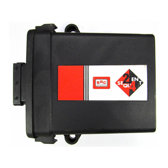
Summary of Contents for BRC Sequent 24
- Page 1 M.T.M. s.r.l. Via La Morra, 1 12062 - Cherasco (Cn) - Italy Tel. ++39 0172 48681 Fax ++39 0172 488237 HANDBOOK on SEQUENT 24 TA010976 - N. 1 - 17 - 11 - 2004...
-
Page 2: Table Of Contents
A - LIST OF THE PINS AND THEIR FUNCTIONS B - LOCATION OF THE ECU PINS C - GENERAL ELECTRICAL DIAGRAM D - INJECTORS CUT DIAGRAM E - PETROL INJECTOR CONNECTION SEQUENT 24 HARNESS RIGHT OR LEFT F - UNIVERSAL 4-PETROL INJECTOR CON- NECTION SEQUENT 24 HARNESS... -
Page 3: Introduction
1. INTRODUCTION signal. The new SEQUENT 24 PC programme is easier to use and completely separated from the 1.1 WHAT IS SEQUENT 24? standard SEQUENT and from the SEQUENT 24 is the BRC sequen- SEQUENT FAST, also as regards tial injection system in the gaseous... -
Page 4: Understanding The Sequent 24 System
ECU. When the communi- dard Sequent and Sequent Fast (as in all the previous systems). cation fails, the two level central that are already familiar to the BRC The rectangular red LED lit informs green LEDs and the rectangular installers. - Page 5 The MAP sensor is identical with the MAP sensor of the Standard SEQUENT, already familiar to the BRC installer. The material differen- ce distinguishing it from the other systems is that in the SEQUENT 24 this sensor is used ONLY DURING THE SELF-MAPPING. During the...
- Page 6 2.9 HARNESS ECU needs this wire to be high- with the utmost care. The SEQUENT 24 harness is slen- potential, programming will be car- In particular, bear in mind that: derer than the previous systems’ ried out with the vehicle running.
- Page 7 BRC sequential systems already on example, in the cut-off, the visuali- different injectors cut on Sequent the market and familiar to the BRC installer. Only the material differen- SSISTED PERSONALISED PROCEDURE ces introduced for SEQUENT 24...
-
Page 8: Engine Water Temperature Sensor
24. In particular, the injectors are simultaneously cut and changeover can be rough while in the Standard Sequent or Sequent Fast it was clean in all conditions. In these cases it is proper to avoid changing over in the most critical conditions that normally are idle speed or con- ditions requiring much torque to the engine. - Page 9 indicates that changing over can be possible at RPM lower than 4000 and with a MAP value close to the idle speed one. - “Changing over in deceleration” indicates that changing over can be possible in deceleration conditions, that is to say with RPM ranging between 2000 and 4000 and a MAP value close to the idle speed one.
- Page 10 5 UTILITIES This chapter will only examine the differences with the previous SEQUENT systems, otherwise you are kindly requested to make refe- rence to the handbooks on the Standard SEQUENT SEQUENT FAST. 5.1 INFORMATION This section allows controlling the updating of the software versions existing on the PC that can be downloaded on the ECU, visuali- sing the software name and version...
- Page 11 • Disconnect the communication cable or • The communication with the PC is still The ECU does not switch off exit from the SEQUENT 24 programme active and wait till the ECU is switched off • Changeover to gas and verify the level visualisation.
-
Page 12: Gas Pressure And Temperature Sensor
ANNEXES A Pins N. PIN OF THE N. PIN OF REMOTE WIRE COLOUR WIRE NAME DESCRIPTION THE ECU CONNECTOR ECU power supply from battery / Note 1 +VBATT injectors current blow-by Ring Black GND-INJ Gas injectors ground Green/Black EVGAS Solenoid valve piloting outlet White/Green INJ1-GAS Gas injector 1 piloting outlet... -
Page 13: Wiring Diagram
ANNEXES C General electrical diagram LPG SEQUENT 24 WIRING DIAGRAM c/o switch Diagnostic Fuse Fuse Level Sensor connector Point Connector Relé Back Solenoid Valve Connector Sequent 24 To connect during is made of mapping of the car Europa Multivalve 4th Petrol... -
Page 14: I Njectors Cut
ANNEXES D Injectors cut diagram... -
Page 15: Annexes
ANNEXES E 4-Petrol injector connection Sequent 24 Harness Right or Left Sequent 24 1° Injector 2° Injector 3° Injector 4° Injector ANNEXES F Universal 4-Petrol injector connection Sequent 24 Harness SEQUENT 24 Inj. 1 Petr. Inj. 1 Petr. Inj. 2 Petr.

Need help?
Do you have a question about the Sequent 24 and is the answer not in the manual?
Questions and answers