
Related Manuals for Mars m2 multi

Summary of Contents for Mars m2 multi
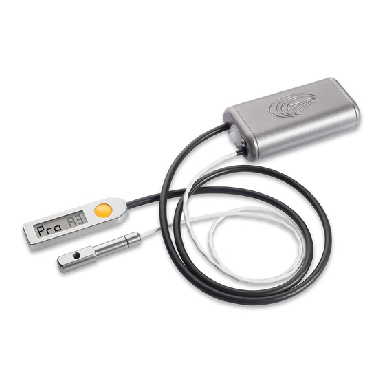
- Page 1 USER MANUAL multi AAD It could save you..More than you think..08.17.08 EN...
-
Page 2: Table Of Contents
CONTENTS Controls Maintenance CONTENTS WARNING 5.1. Control basics 9.1. Cutter replacement Introduction 5.2. Switching the device on and off 9.2. Filter replacement 5.2.1. Switch on sequence 9.3. Battery 1.1. General description 1.2. Operating principle 5.2.2. Switch off sequence 9.4. Annual inspection 5.3. -
Page 3: Warning
WARNING Skydiving is a dangerous activity that can result in serious or even fatal injury. To reduce these risks, it is necessary to have training and experience. Using the m multi automatic activation device when skydiving can significantly reduce these risks. Never rely solely on the m multi, since it is not the primary tool for opening of your parachute. -
Page 4: Introduction
1. Introduction 1.1. General description Thank you for purchasing the m multi AAD and we hope that you never find yourself in a situation in which you would need to use it. Simply switch on the m multi in the chosen profile before the first jump and it will quietly guard your safety from that moment until it is switched off again. The “AAD”... -
Page 5: Construction
2. m multi description 2.1. Construction The m multi is designed to best meet the requirements for durability and correct operation in all situations. It strives not to restrict the skydiver. It works with minimum power consumption, which allows it to maintain sufficient capacity of the energy source for its entire service life without having to replace the battery. -
Page 6: Control Unit
2. m multi description 2.3. Control unit The body of the control unit is made of stainless steel and is connected to the processing unit by a flexible cable. The unit has a display for the various icons and a control button. Only press the control button with the pad of your finger! Display... -
Page 7: Profiles
3. Profiles 3.1. Description Profile is a set of parameters that determine the conditions for activation of the m multi device. The most important parameters are the acti- vation altitude and the fall rate. The parameters of the individual profiles are fixed. The user may select and set a profile depending on his skills, used parachute and sports performance or focus. - Page 8 3. Profiles 3.2.2. INTERMEDIATE (Int) The INTERMEDIATE profile is designed for basic training of advanced students and AFF. It is activated when the height above the landing loca- tion is lower than approx. 330m / 1 100ft and fall rate is higher than approx. 20m.s / 45mph.
- Page 9 3. Profiles 3.2.4. CANOPY PILOTING (CPi) The CANOPY PILOTING profile is primarily intended for the Canopy Piloting sports discipline. The profile is used only for the most experienced pilots with extremely quick parachutes and vast experience. It is activated when the height above the landing location is lower than approx. 270m / 885ft and fall rate is higher than approx.
-
Page 10: Profile Charts
3. Profiles 3.3. Profile charts TANDEM 900m 2,950ft approx. approx. 2,950 alt - lock 2,625 2,295 610m 2,000ft approx. approx. 1,970 >35m/s >78mph approx. approx. STUDENT INTERMEDIATE PROFESSIONAL CANOPY PILOTING 1,640 450m 1,475ft 450m 1,475ft 450m 1,475ft 450m 1,475ft approx. approx. -
Page 11: Profile Parameters
3. Profiles 3.4. Profile parameters 3.4.1. m multi STUDENT (Stu) 3.4.4. m multi CANOPY PILOTING (CPi) Altitude lock (Alt-Lock) approx. 450m / 1 475ft Altitude lock (Alt-Lock) approx. 450m / 1 475ft Activation zone begins (Top) approx. 330m / 1 100ft Activation zone begins (Top) approx. -
Page 12: Adjust Description And Use
3. Profiles 3.5. AdJUSt description and use The individual profiles and their activation parameters are fixed in the process of manufacture. Some users may prefer a higher activation altitude, which gives them more time to deal with an emergency in case of activation. In some countries or at some dropzones a higher activation altitude may be required by local regulations. -
Page 13: Operating Mode
4. Operating mode 4.1. Description The m multi device may be switched on in several modes. The mode is selected when the device is switched on and remains active until it is switched off again - the selection is not permanent. The various modes are used to distinguish the type of jump and they determine the device behavior. BASIC mode is used most often - when the skydiver performs the jump at an airport (dropzone) and the aircraft take-off point and the landing location are thus the same - they are at the same elevation. -
Page 14: Offset Hi Mode
4. Operating mode 4.2.2. OFFSEt HI - mode OFFSET HI mode is designed for situations when the landing location is higher (elevation) than the elevation at which the device was switched on (take-off point of the aircraft). It is necessary to set the elevation difference of the landing location in the range of approx. +/- 999m / Reminder: This is a temporary setting for one jump only! +/- 2 990ft. -
Page 15: Offset Lo Mode
4. Operating mode 4.2.3. OFFSEt LO - mode OFFSET LO mode is designed for situations when the landing location is lower (elevation) than the elevation at which the device was switched on. Reminder: This is a In this mode, you can set the elevation difference of the landing location in the range of approx. +/- 999m / +/- 2 990ft. temporary setting for one jump only! The settings can only be done when switching on the device. -
Page 16: Examples Of Using Modes
4. Operating mode 4.3. Examples of using modes 4.3.1. BASIC mode - example BASIC mode shall be used always, when the skydiver takes off and lands on the same location, usually drop zone (takes off and lands at the same elevation). The display shows: Switched on in the BASIC mode with STUDENT (Stu) profile 4.3.2. -
Page 17: Offset Hi Mode - Sequence
wait offset feet offset feet click >> & << wait 4. Operating mode click >> & << wait offset feet offset feet click >> & << Switch on with 1000 feet + offset Switch on with 1000 feet - offset wait Switched on with OFFSEt +1000ft click... -
Page 18: Offset Lo Mode - Setting And Example
4. Operating mode 4.3.3. OFFSEt LO mode - setting and example Limit warning! The OFFSEt LO mode can only be used locally on the same isobar! Example: The landing location is about 175 m below the point at which the device was turned on (take-off point). Briefly press the yellow button on the control unit, GO-ON sign appears (for 2 seconds). -
Page 19: Offset Lo Mode - Sequence
offset feet wait offset feet click click >> & << >> & << 4. Operating mode wait wait click >> & << wait offset feet offset feet click click >> & << >> & << Switch on with 1000 feet + offset Switch on with 1000 feet - offset wait wait... -
Page 20: Controls
click >> & << wait 5. Controls click >> & << wait 5.1. Control basics wait Control of the m multi device is very simple. The only control is the yellow button on the control unit (Section 2.3). Always depress the button shortly and release it immediately. -
Page 21: Changing The Profile
5. Controls Change scale Set Adjust Change actual pro le meter to feet to + 200 feet from Professional to Sudent Change actual profile from PROFESSIONAL to STUDENT 5.3. Changing the profile click click click The possibility to change the profile of the device is one >>... -
Page 22: Info
5. Controls 5.4. INFO 5.4.3. Meaning of individual letters It is possible to access the INFO menu with the device switched on as well as off. d - deploy altitude of the last jump All the useful information is stored under individual letters. J - total number of jumps G - Gravity index of the last jump 5.4.1 Access INFO with device ON... -
Page 23: Gravity Index
5. Controls 5.4.4. Gravity index G - Gravity index is the percentage of the highest achieved fall rate in the activation zone during the last jump, when 100 % is the activation speed of the currently used device profile. After landing, the skydiver may check how close he was to the device activation limit during his flight on the parachute in the activation zone. -
Page 24: Setup
6. SEtUP 6. SEtUP The SEtUP may be entered when switching on the device. SEtUP allows access to the following device settings and their permanent change. - SCALE (setting the units meter / feet) - ProFilE (setting the profile Stu, Int, Pro, CPi, TAn) - AdJUSt (increase the activation height) 6.1. -
Page 25: Scale Setting Sequence
6. SEtUP Change scale Set Adjust Change actual pro meter to feet to + 200 feet from Professional to S Change SCALE meter to feet 6.1.1. SCALE setting sequence click click >> & << >> & << blank LCD - device is off blank LCD - device is off blank LCD - device is o wait... -
Page 26: Profile Setting Descrption
6. SEtUP 6.2. ProFilE setting description The setting is performed when switching on the device. Briefly press the yellow button on the control unit, GO-ON sign appears (for 2 seconds). Do not hold the button, depress it only briefly!!! During the time the GO-ON sign is displayed, immediately after it comes on, depress the yellow button briefly once again. -
Page 27: Profile Setting Sequence
6. SEtUP Set Adjust Change actual pro le to + 200 feet from Professional to Sudent Change actual profile from PROFESSIONAL to STUDENT 6.2.1. ProFilE setting sequence click click << >> & << >> & << blank LCD - device is off blank LCD - device is off wait wait... -
Page 28: Adjust Setting Description
6. SEtUP 6.3. AdJUSt setting description The setting is performed when switching on the device. Briefly press the yellow button on the control unit, GO-ON sign appears (for 2 seconds). Do not hold the button, depress it only briefly!!! During the time the GO-ON sign is displayed, immediately after it comes on, depress the yellow button briefly once again. -
Page 29: Adjust Settings Sequence
wait wait 6. SEtUP Change scale Set Adjust Change actual pro le click click >> & << >> & << meter to feet to + 200 feet from Professional to Sudent wait wait AdJUSt setting on + 200ft 6.3.1. AdJUSt setting sequence with example (setting A2) feet x100 click... -
Page 30: Important Limits And Limit Modes
After the altitude lock is unlocked, the aircraft can be pressurized. The aircraft must not be pressurized to a pressure greater than the ambient atmospheric pressure corresponding to approx. 450m / 1 475ft or approx. 900m / 2 950ft. If there are m2 multi devices onboard the aircraft with altitude locks preset to approx. -
Page 31: Important Operation Principles
click click feet x100 click 7. Important limits and limit modes >> & << >> & << wait >> & << blank LCD - device is off blank LCD - device is off wait wait wait feet x100 feet x100 wait wait blank LCD - device is off... -
Page 32: Installation
The m multi automatic activation device must be installed into an original kit supplied by the MarS company and installed in the container directly by the manufacturer of the container and the harness or by an authorized rigger. During the installation, the rigger... - Page 33 8. Installation The thick cable of the control unit shall always be stowed as second onto the already coiled thin cable. If the m multi device body is stowed in such a Cable of Control Unit way that the thick cable is above the thin cable, coil the cable counterclockwise (when looking from the front).
- Page 34 8. Installation The cables must not be stowed in the pouch determined for the device body, nor shall they be stowed (partially) under the device body. There is a risk of damaging the cables. Stow the cutter and the control unit in accordance with the Manual provided by the container manufacturer so that in both cases there is at least minimum space for the cables.
-
Page 35: Securing Closing Loop
8. Installation 8.2. Securing closing loop Variation 1 Variation 2... - Page 36 MarS a.s. or any authorized dealer to perform an overall analysis. In such case the cutter will be replaced by the manufacturer or authorized dealer and the functional device will be sent back to the user within 14 day of having received the device.
- Page 37 9. Maintenance 9.2. Filter replacement After contact with water, it is necessary to replace the air filter built into the m multi device body. The filter serves as a barrier providing protec- tion against contamination. Never use or store the m multi device without a filter.
- Page 38 9. Maintenance 9.3. Battery The m multi device is designed to last its whole service life without the need to replace battery. If for any reason the battery fails, it must by replaced by the manufacturer. In case the battery indicates for example 1 % remaining, there is no need to worry, there is still enough reserve power. 100 % is displayed only the first time the m multi is switched on by the manufacturer.
- Page 39 10. Technical data 10.1. Basic technical data Total weight ................... approx. 220g Length, width, height of the processing unit ......approx. 85mm x 45mm x 23mm Length, width, height of the control unit ........approx. 63mm x 18mm x 5mm Thickness, length of the cutting unit ...........
- Page 40 11. Disclaimer MarS a.s. dedicated great care and attention to the development, laboratory testing, field testing and to the m multi device properties. The goal was and still is to provide users with maximum comfort and safety when using the automatic activation device.
- Page 41 (X-ray) may be different depending on the parachute container. All parts of device are not subject to any transport regulations. The m multi parts: 1. central unit, 2. control unit, 3. cutter, 4. control unit cable, 5. cutter cable X-ray card Packed in a box MarS a.s., Okruzni II 239 569 43 Jevicko, Czech Republic mars@marsjev.cz phone +420 461 353 841 www.m2aad.com...
Need help?
Do you have a question about the m2 multi and is the answer not in the manual?
Questions and answers