AVE VSI-PRO Operation Manual
Video serial cash register interface
Hide thumbs
Also See for VSI-PRO:
- Operation manual (84 pages) ,
- Instruction manual (1 page) ,
- Operation manual (108 pages)

Related Manuals for AVE VSI-PRO


Summary of Contents for AVE VSI-PRO
- Page 1 VSI-PR VSI-PR O O O O O VSI-PR VSI-PR VSI-PR Version 13 VIDEO SERIAL CASH REGISTER INTERFACE Operation Manual June 2008...
- Page 2 2000 West Governors Circle Suite E, Houston, Texas 77092 Tel: 1-281-443-2300 Fax: 1-281-443-8915 Email: sales@aveusa.com http://www.americanvideoequipment.com AVE Thailand Co., Ltd. 2000-2008 AVE Thailand Co., Ltd. 147 Soi On-Nut 44 Sukhumvit 77 Rd., Suan Luang Bangkok 10250,Thailand Tel: 662-331-9364, 331-9285 Fax: 662-331-9554 Email: ave@avethailand.com...
-
Page 3: Table Of Contents
4. User Front Panel Controls...13 4.1 Front Panel Controls...13 5. Programming...15 5.1 Getting Started...15 5.2 Main- Menu Programming...15 5.3 Register Select...15 Section A : VSI-Pro Version 13.00...16 TCPIP...16 Section B : VSI-Pro Version 13.24...21 5.4 Screen Setup...23 Text Grayscale...23 Background Gayscale...23 Clock...24... - Page 4 Table 1 : Pin-Out of the DB-9 Female Connector on the VSI-Pro RS-232...10 Table 2 : RS-232 DB-9 Pin-Out vs VSI-Pro DB-9 Pin-Out...10 Table 3 : Pin-Out of the DB-9 Female Connector on the VSI-Pro RS-422 / RS-485...11 Table 2C : DB-9 Pin-Out...59 Table 3C : RJ-45 Pin-Out...59...
- Page 5 Figure 50-B : Omega 2000 Sub-Menu...22 Figure 51-B : Schlumberger Sub-Menu...22 Figure 52-B : Sharp 750 ER - 01PU...22 Figure 53 : VSI-Pro On-Screen Setup Menu...23 Figure 54 : Clock Display Sub-Menu...24 Figure 55 : On-Screen Titler Sub-Menu...25 Figure 56 : Text Display Sub-Menu...25 Figure 57 : Communication Sub-Menu...28...
- Page 6 Figure 1H : Front of TCPIP232 Adapter...68 Figure 2H : Rear of TCPIP 232 Adapter...68 Figure 3H : VSI-Pro Connections with TCPIP 232 Adapter...68 Figure 4H : Pin-Out for TCPIP 232 Adapter to VSI-Pro...68 Figure 1 I : Hard Alarm Output...69...
-
Page 7: Introduction
This utilizes a direct connection via RS-232 from a laptop to the VSI-Pro. Complete VSI-Pro settings can be saved on the laptop and uploaded to the VSI-Pro at will. This is mainly used for dealer maintanence or for single station user programming. -
Page 8: Features & Specifications
...Gray scale and border selection from front panel ...Built-in test mode ...Built-in cash register demo ...Upload/download programming to a PC or another VSI-Pro ...Data captured either to the memory or to the serial port ...Local Firmware Downloadable ...Local / Remote Programming via PC Software ...Supports Hydra/Regcom/Networker/Vnetworker networking communications products... -
Page 9: 2.2 Specifications
Temperature Rating Humidity Weight Metal Enclosure Beige Maximum Size with Connectors Packed in White Box with Manual VSI-Pro VIDEO SERIAL INTERFACE 1V P-P Terminated 75 ohms +/- 20% 1V P-P Terminated or Unterminated better than 50dB better than 7MHz 9-12VDC 170mA... -
Page 10: Connections
VSI-Pro. The BNC video output goes out to the video system (VCR, DVR, quad, switcher, multiplexer, or monitor). This connection is shown in Figure 3. The video output from the VSI-Pro is 1[V] Peak to Peak into a 75 [ohm] load. -
Page 11: 3.1 Rs-232 Serial Input
3.1 RS-232 SERIAL INPUT The VSI-Pro accepts serial data via the DB-9 female connector located on the rear of VSI-Pro. This connector is similar to “AT” type computer RS232 serial ports and the pin out is identical. Table 1 shows the standard pin out for VSI-Pro RS-232 female connector. -
Page 12: Figure 4 : Vsi-Pro Connections
CONNECTIONS PIN # Table 3 : Pin-Out of the DB-9 Female Connector on the VSI-Pro RS-422 / RS-485 RS-232 Direct or ECR Interface CASH REGISTER VSI-Pro VIDEO SERIAL INTERFACE FUNCTION Alarm Out 1 Open Collector Transisitor No Function No Function... -
Page 13: User Front Panel Controls
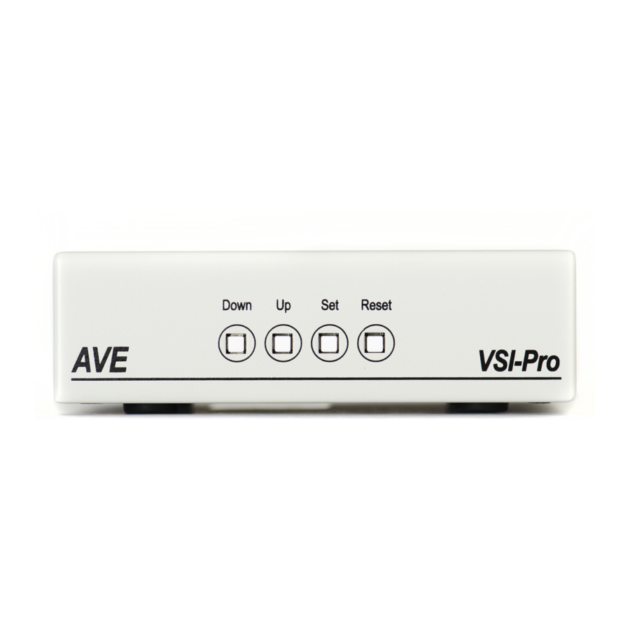
4. USER FRONT PANEL CONTROLS The VSI-Pro is programmed by pressing and releasing specific combinations of the four front panel push- buttons. Via these four simple buttons, all of the powerful programming features of the Text Inserter are available. A video source and a monitor must be connected in order to see the programming menus. -
Page 14: Figure 8 : Four Front Panel Push Button Of Vsi-Pro (Set)
USER FRONT PANEL CONTROLS Changing the Horizontal Position Down Reset Figure 7: Four Front Pannel Push Buttons of VSI-Pro (Up) 1. Press and hold the “Up” button. 2. Press and release the “Reset” button. 3. Release the “Up” button. 4. Press “Down” or “Up” to move the text block. -
Page 15: Programming
5.1 GETTING STARTED To access the main-menu of the VSI-Pro, simultaneously hold down the “Down” & “Up” buttons and press and release the “Reset” button and then release the “Down” & “Up” buttons. This will take you to the main programming menu. -
Page 16: Figure 10-B : Tcpip Sub Menu
TCPIP232 Adapter or VSI-Pro and data will be lost and would not be suitable for security moni- toring anyway. The VSI-Pro has a set of powerful data dump modes that compatible with the TCPIP232 Adpater. If large data packets need filtering or special formats are... -
Page 17: Figure 11-A : Addressable Vsi Sub-Menu
Press the “Up” or “Down” button to move the cursor to “AD4323” and press “ Set ”. No menu will apprear and merely sets the VSI-Pro to support the special protocol of this model. Press the “Up” or “Down” button to move the cursor to “ADS”... -
Page 18: Figure 17-A : Edacom Sub-Menu
DEVICE Choices: PRINTER, CONSOLE,CSL OLD DEVICE ADDRESS Choices: ANY, 01, 02, 03,..., 17 VSI-Pro VIDEO SERIAL INTERFACE Press the “Up” or “Down” button to move the cursor to “GILBARCO” and press “ Set ”. The GILBARCO menu will appear: Press the “Up” or “Down” button to move the cursor to “IBM 3151 TERMINAL”... -
Page 19: Figure 25-A : Micrelec Ms Series Sub-Menu
DEVICE ADDRESS: MODE: EXIT Figure 28-A: MICROS IDN NETWORK Sub-Menu DEVICE Choices: PRINTER, VIDEO VSI-Pro VIDEO SERIAL INTERFACE DEVICE ADDRESS Choices: ANY, 01, 02, 03,...,13, 14, 15 MODE Choices: EMULATE,TAP Press the “Up” or “Down” button to move the cursor to “MICROS ISN NETWORK”... -
Page 20: Figure 31-A : Nixdorf Beetle Sub-Menu
Choices: ACK , TAP Press the “Up” or “Down” button to move the cursor to “PANASONIC” and press “ Set ”. The PANASONIC menu will appear: VSI-Pro VIDEO SERIAL INTERFACE Figure 33-A: PANASONIC Sub-Menu MODEL Choices : 6000, 7000, 8000... -
Page 21: Section B : Vsi-Pro Version 13.24
JOURNAL EMULATING RECEIPT EMULATING Figure 39-A: VERIFONE Sub-Menu SECTION B: VSI-Pro V13.24 Press the “Up” or “Down” button to move the cursor to “REGISTER SELECT” and press “ Set ”. The REGISTER SELECT menu will appear: VSI-Pro VIDEO SERIAL INTERFACE Press the “Up”... -
Page 22: Figure 49-B : Nixdorf Beetle Sub-Menu
MODEL EXIT Figure 48-B: MODEL E90 Sub-Menu VSI-Pro VIDEO SERIAL INTERFACE Press the “Up” or “Down” button to move the cursor to “NIXDORF BEETLE” and press “ Set ”. The NIXDORF BEETLE menu will appear: Figure 49-B: NIXDORF BEETLE Sub-Menu Press the “Up”... -
Page 23: 5.4 Screen Setup
Master Reset. CLOCK To program the clock's functions, press the “Up” or “Down” button to move the cursor to “CLOCK” and press “Set”. The following menu will appear: VSI-Pro VIDEO SERIAL INTERFACE TEXT GRAYSCALE BLACKGROUND GRAYSCALE HORIZONTAL POSITION... -
Page 24: On-Screen Titler
If the T/D LOCKING is turned on, make sure that the time format selected is the same as the register’s time/date format. If the T/D LOCKING is turned on, the VSI-Pro will monitor the incoming data string. If it finds a valid time and date in one or two consecutive lines, it will set the clock to whatever time/date it finds. -
Page 25: Titler
TITLE The VSI-Pro gives you the option of a 40-character display for easy register identification in addition to the actual register transaction data. To create a title, press the “Up” or “Down” button to move the cursor to “TITLE” and press “Set”. You will see a row of 40 boxes and the first box will be flashing. -
Page 26: Screen Blank
Choices: NONE, 6, 12, 20, 30, 60, 120, 180, 300 This is the amount of time that the VSI-Pro text display will remain on-screen after a transaction before blanking itself off (not the video picture, just the register transaction data) until the next transaction. -
Page 27: Space Compress
Space Compress allows you select the number of maximum spaces next to each other in a line. The selections are 1,2,3,4,5 and OFF. If you select “1” then if three spaces are shown on the receipt the VSI-Pro will delete 2 and only show 1 space between characters on the video and on the output data to the DVR. -
Page 28: 5.6 Communication
This was discussed briefly in the section under “REGISTER SELECT” and will be fully explained here. When you choose your register type under the REGISTER SELECT menu, this automatically formats the VSI-Pro to the appropriate settings needed to communicate with your register. There may be times when you will need to amend these settings for a specific register. -
Page 29: Parity
Choices: ON, OFF Auto Linefeed makes the VSI-Pro append a CR/ LF after each displayed line. The default of this function is “ON”, but if you would like to disable it then press the “Up” or “Down” button to move the cursor to “AUTO LINEFEED” and press “Set”. - Page 30 There may be situations where you do not want cashiers or other employees to know what triggers an exception. In this case, the VSI-Pro provides a separate output that will send data to a remotely located serial printer. If you turn the on-screen display off and the output on and you have a remote serial printer hooked up to the VSI-Pro, then, whenever an exception is reported, it is sent out to the serial printer only.
-
Page 31: Exception History
Define “NOSELL” as an exception string In Exception NO. 2 , DISPLAY to be “ON”, and define OPERATOR “IN”. NOTE For any exception you must program Display “ON” for any exception data to be saved in the Exception History. VSI-Pro VIDEO SERIAL INTERFACE EXCEPTION HISTORY SET EXCEPTION OUTPUT... -
Page 32: Time Search
Choices: 1 through 32 TIME SEARCH TIME SEARCH SETTING USING TIME SEARCH FUNCTION Press the “Up” or “Down” button to move the cursor to will appear: VSI-Pro VIDEO SERIAL INTERFACE NONE DMS-3001 DVR-3011.3021 EXIT Figure 61: DVR Selection Sub-Menu DEST ID... -
Page 33: Figure 64 : Vsi-Pro With Dvr Connections
EXAMPLE Define “NOSELL” as an exception string In Exception No. 2 , DISPLAY to be “ON”, and define OPERATOR “IN”. If the screen is displayed “NOSELL”, the VSI-Pro will keep this displayed line on Exception History. CASH REGISTER OUTPUT EXCEPTIONS This selection allows you to have the buffered exceptions sent out for printing. -
Page 34: Figure 65 : Set Exception Sub-Menu
Choices: ON, OFF The OUTPUT controls the RS-232 data from the VSI-Pro. Typically this is sent to a remote Serial Printer to provide a hard copy of Exceptions with time and date on it. This data can also be sent out to a computer with appropriate software and give you the ability to analyze data. -
Page 35: Scroll Matching
VSI-Pro. This can be used to automatically search a compatible DVR, upload to a PC to save or print out and view on screen on the VSI-Pro. This setting allows the user to enable or disable this feature as to conserve memory allocation for other features. -
Page 36: Programming Note
EXCEPTION STRING The VSI-Pro compares the data that is printed to video to the data entered in the Exception String. The Exception String can also be used without a defined range. Example of this would be to assign a word “ VOID” as an exception. - Page 37 “out of the range” calculations. With this version of the VSI-Pro, you can define ranges for your exceptions and have the VSI-Pro alarm when an exception falls within the range’s parameters or outside the range of the two numbers. The choices are “IN”, “OUT”, and “NONE”.
- Page 38 LESS THAN This example will show you how to program an exception to flag all sales in Department 6 of less than $100. 00: Exception No. 4 Display Output ON or OFF Exception String Range 0000.01-0099.00 Operator VSI-Pro VIDEO SERIAL INTERFACE...
-
Page 39: Figure 66 : Alarm Output Sub-Menu
Choices: 1, 2, 3, 4, 5, 6, 7, 8, 9, 10, 11, 12, 13, 14, 15, 16, 17, 18, 19, 20, 21, 22, 23, 24 The VSI-Pro allows you up to 16 alarms that may be used with any of the user programmed exceptions. However there are only 2 hardwired alarm outputs and these correspond to Alarm 1 &... -
Page 40: Alarm Trigger
Choices: 1, 2, 3, 4, 5, 6, 7, 8, 9, 10, 11, 12, 13, 14, 15, 16, 17, 18, 19, 20, 21, 22, 23,24 , 1-12, 13-24, 1-24 An Alarm Trigger is the source of activity programmed to activate a certain alarm. The alarm trigger tells the VSI-Pro what exception to use to trigger the alarming device or the on-screen flag. -
Page 41: Flag Type
Press the “Up” or “Down” button to cycle through the values and press “Set” when the desired value is displayed. Selecting “OFF” will not display any exception text on the video output. VSI-Pro VIDEO SERIAL INTERFACE DISPLAY TEXT OUTPUT TEXT... -
Page 42: Set Triggered Text
5.9 TEST/DEMO MODE The TEST/DEMO MODE provides you with several ways to test the VSI-Pro and demonstrate its capabilities as a cash register interface. Press the “Up” or “Down” button to move the cursor to “TEST/DEMO MODE” and press “Set”. -
Page 43: Port 1 Test
RECEIVE [ RX ] TEST The purpose of this test is to determine that if VSI-Pro is receiving the data or not. Press the “Up” or “Down” button to move the cursor to “RECEIVE [ RX ] TEST”. The following display will appear (example only): Receiving data will be appear in three sperate lines, scrolling from right to left. - Page 44 “Down” button. RX / TX TEST In the RX/ TX test the VSI-Pro echos whatever it receives. Press the “Up” or “Down” button to move the cursor to “RX/ TX TEST” and press “Set”. The following display will appear (example only): Press “Set”...
-
Page 45: Data Capture
CAPTURE TO MEMORY This feature allow you to store the data in the internal memory of VSI-Pro. You can store up to 20 kilobytes of data in the internal memory of VSI-Pro. Power up the VSI-Pro for 24 hours prior to download of data. This will provide VSI- Pro’s internal battery a full charge to hold data in its memory. -
Page 46: Register Demo
If you connec the VSI-Pro to a cash register and it sends data to the VSI-Pro during this demo mode then the demo mode will also be disabled until you press “Reset”... -
Page 47: Figure 79 : Download/Upload Setup Using Vsi-Pro To Vsi-Pro
79, you can get the programming menus for both VSI-Pros on the screen at the same time. Use the front panel shortcut to position the text block from the PROGRAMMED VSI-Pro on the left side of the screen. To do this, press and hold down “Up”, then press and release “Reset”... -
Page 48: Figure 81 : Download Setup Sub-Menu & Display
VSI-Pro’s. Now go to the main-menu of the previously UNPROGRAMMED VSI-Pro on the right side of the screen. Enter the EXCEPTIONS menu. You should see your exceptions and other programmed data just as they were on the original PROGRAMMED VSI-Pro. -
Page 49: Download/Upload Setup Using A Pc
DOWNLOAD/UPLOAD SETUP USING A PC You can use a Laptop PC and AVE’s IC or equivalent communications program to store data from a VSI-Pro to a file. This file can then be uploaded to other VSI-Pro units with the same software revision level. Use 4800 baud for the PC’s baud rate.NOTE: This feature is only available to like versions and release. -
Page 50: Figure P2 : Remote Menu
Figure P2 Remote Menu Click on “Set Comport”. If the VSI-Pro is in the “Baudrate Detection” Mode then you can set any baud rate and the VSI-Pro will self configure. However if the VSI-Pro is already set to a baud rate you must select the exact baud rate and communication configuration in the VSI-Pro for connection to occur. -
Page 51: Figure P3 : File Menu
Communication Cable Pin Out The Com cable is RS-232 from the PC or laptop to the VSI-Pro as follows. This cable can be no more than 100’ but if additional length is required you will need a set of the AVE RS-232 to RS-422 adapter which will extend the range to 3000’... -
Page 52: Update Firmware
Update Firmware of VSI-Pro You have to connect the VSI-Pro with a Serial Program Terminal such as HyperTerminal, IC etc. But advise to use HyperTerminal.First, you have to set the baud rate HyperTerminal to 19200 See PC Windows below to verify proper HyperTerminal setup. -
Page 53: Figure P7 : Port Settings Menu
PROGRAMMING Click File ==> Properties You will see the configuration frame and then click. Figure P6 Connect To Menu Choose Bits per second to 19200 and press connect. Figure P7 Port Settings Menu... -
Page 54: Figure P8 : In-System Programming Display
To do this just power up the VSI-Pro or press reset while the terminal program is connected and you will see the prompt messages as above window. -
Page 55: 5.11 Help
2. If VSI-Pro was working and stopped, power cycle the system. Turn off the register, unplug the power to the N2RS, and unplug the power to the VSI-Pro. Now power up the system, plug in the VSI-Pro and the N2RS. Turn on the register and do a transaction. - Page 56 1. Darken the gray scale of the characters. 2. The VSI-Pro requires the input video signal to be 1V P-P +/-20%, terminated @ 75ohms. If the voltage is too high or low, then the VSI has trouble syncing the text to the video. Use an amplifier such as AVE’s VDA-601 to get the proper level.
-
Page 57: Appendix B : Pc-Based Cash Register
DB9 or DB25 type connectors. However parallel printers generally use Centronics type connectors, but on the cash register side use DB25. If it is a serial printer then you can use an AVE Triport DB9 or Triport DB25. -
Page 58: Figure 1C : Ds-20-Of Vsi-Pro Pcb Rack
OPERATION The Regcom receives RS-232 data from a cash register, VSI-Pro, Interface Adapter, or ECR Interface card inside the cash register. It then stores this data in its buffer before sending it on to the Hydra via the RS-485 network. -
Page 59: Table 2C : Db-9 Pin-Out
HYDRA and REGCOM REGCOM RS232 / RS485 INTERFACE DEVICES OVERVIEW The Regcom is an interface device that allows the connection of multiple cash register terminals to a master unit for the purpose of transaction logging. CONNECTION DIAGRAM Regcom RS-232 Cash Register NETWORK TERMINATION The device at end of the network must be “TERMINATED”. -
Page 60: Specifications
Data bits Parity Stop bits Network Parameters Standard Max line length Cable type VSI-Pro VIDEO SERIAL INTERFACE (120 Ohm impedance, twisted pair) RJ-45 Pin 4 Pin 5 Table 4C : RS-485 Network Data Cable Wiring 9-12V DC <200mA @ 12 V... -
Page 61: Figure 3C : Hydra / Regcom Front Panel
Status light B illuminates to indicate the Regcom is correcly connectly connected via the RS-485 network to the master unit. Figure 3C: Hydra / Regcom Front Panel VSI-Pro VIDEO SERIAL INTERFACE Table 9C: Address Selection Figure 4C: Hydra / Regcom Rear Panel... -
Page 62: Appendix Drs-485 Networker
The RS-485 Networker controls this handshaking signal to the VSI-Pro and when the networker is addressed by the host the data from the VSI-Pro is sent to the host. The data from each Networker is saved to a log file on the PC which can be read later as a data history from each VSI-Pro. -
Page 63: Appendix E : Pc Software With Cash Register
16 VSI-Pros on a single RS-485 network. The Vnetworker products connects to the cash register, the VSI-Pro and the RS-485 networker and controls the flow of data from all de- vices. This device utilitzes the “Hardware” handshaking RTS line of the VSI-Pro to control reading register data and signally the VSI-Pro that the user requires programming upload. - Page 64 All functions of the VSI-Pro locally operate normally and as a stand alone VSI-Pro. However the Vnetworker is placed between the VSI-Pro and the register so it can disable the serial connection to the VSI-Pro and control it for programming useage.
- Page 65 This new function allows the user to select the appropriate VSI-Pro on the network with the Select Address setting. Once this is done you then click “Programming”. The Vnetworker will then signal the VSI-Pro to exit the register interface mode and go to the programming mode. Note: While in this mode all data from the cash register will not be stored or displayed in the VSI-Pro and will be lost.
-
Page 66: Appendix G : Vsib Installation
VSI-Pro. A special cable is connected between the VSI-Pro and the VSIB so all on-screen programming is done via the VSIB but the controls and menus are the same as the VSI-Pro. Therefore after connec- tion, the programming will be identical to this manual. The VSIB must be ordered independently for any of the above supported languages and the language must be specified. -
Page 67: Appendix H : Ecr Interface Cards
RS-232 data. This RS-232 data is then connected directly to the VSI-Pro for display. It also can be connected directly to the Regcom to send up to 16 cash register’s data on a central collection PC or DVR. -
Page 68: Appendix I : Tcpip 232 Adapter
APPENDIX I TCPIP 232 ADAPTER Interfacing the VSI-Pro to the cash register TCP/IP network requires the TCPIP 232 Adapter along with the VSI-Pro. The IP address of the cash register is programmed into the TCPIP 232 Adapter via on-screen programming. The cash register LAN cable is plugged into the adapter and the supplied additonal LAN cable is then plugged into the cash register. -
Page 69: Appendix J : Hard Alarm Output
The VSI-Pro provides two open collector transistor alarm outputs to trigger alarming devices. These are Alarm 1 & 2 in the Alarm menu. Upon an Exception, a VSI-Pro can be programmed to trigger a VCR to go to its fastest record time, have a Quad go full screen, home a switcher, trigger a preprogrammed PTZ, or provide visual or audible alarms. -
Page 70: Appendix Kregister Select
GILBARCO GILBARCO IBM3151 TERMINAL JETSORT MEMS-5 MICRELEC MICROMAX MICROPOS MICROS NIXDORF NORAND PANASONIC Table 1I: VSI-Pro Version 13.00 Register Select Menu VSI-Pro VIDEO SERIAL INTERFACE REGISTER SPECIAL CABLE CABLE FUJ 9920 G-SITE TCRG/2 TCR15(OLD) MASTER SERISE 9500 LOCALVSS IDN NETWORK... - Page 71 VSI-PRO VERSION 13.00 REGISTER SELECT MENU (CONTINUED) MODEL POLE DISPLAY SHARP SICOM SUNTRONIC SWEDA SWINTEC TOLEDO UNITOUCH UNIWELL VERIFONE VSI-DRS Table 1I: VSI-Pro Version 13.00 Register Select Menu (Continued) VSI-Pro VIDEO SERIAL INTERFACE REGISTER SPECIAL CABLE 2590 3100,3110 3220,3221,3250 3310,3311,3550 A-460,A-470 A-550,A-570 A-610,A-650 A-750 A-770...
-
Page 72: Table 2I : Vsi-Pro Version 13.24 Register Menu
HUTH T 400/T500 KOPPENS GASPUMP NIXDROF BEETLE ODOMETER OMEGA 2000 Q-MATIC SAMSUNG SRP 350 SCHLUMBERGER SHARP 750 ER -OLPU SIEMENS UNIPAR UP3000 Table 2I: VSI-Pro Version 13.24 Register Select Menu VSI-Pro VIDEO SERIAL INTERFACE REGISTER SPECIAL CABLE REGISTER SELECT SPECIAL MODE... -
Page 73: Appendix L : Master Reset
VSI-Pro. Upon powering up the VSI-Pro for the first time, if the battery is depleted the master reset should be done. However in some cases the Time/Date display may not have the correct or legible characters. If this occurs, go to the Clock programming section of the menu and reset the clock and program the correct time. -
Page 74: Appendix Mlimited Warranty
Seller’s written service policy. No Product shall be returned without Seller’s prior written consent. VSI-Pro VIDEO SERIAL INTERFACE LIMITED WARRANTY (Terms and Conditions) -
Page 75: Appendix N : Notes
RETURNS AVE products are fully inspected and carefully packed to ensure you are delivered a quality product in good condi- tion. If you are not fully satisfied with our product, returns of standard stocking items with no restocking fee can be made within thirty (30) days of invoice to Buyer. - Page 76 ASIA AVE Thailand Co., Ltd. 147 Soi On-Nut 44 Sukhumvit 77 Rd., Suan Luang Bangkok, 10250 Thailand Tel: 662-331-9364, 331-9285 Fax: 662-331-9365 Email: ave@avethailand.com www.avethailand.com (English) www.ave.co.th (Thai) NORTH AMERICA American Video Equipment (AVE) 2000 West Governors Circle, Suite E...
Need help?
Do you have a question about the VSI-PRO and is the answer not in the manual?
Questions and answers