
Summary of Contents for OpenTech Alliance INSOMNIAC CIA K-500
- Page 1 INSOMNIAC CIA K-500 Keypad Installation Manual P/N CIA-575-001 Revision 1.0 Date Code: 1-1-2018...
-
Page 2: Table Of Contents
CIA-575-001 Rev 1.0 Table of Contents SPECIFICATIONS: ........................3 INSTALLATION ......................... 4 General: ..........................4 Physical Installation and Mounting ..................4 Wiring Connections: ....................... 6 PWR/RS485 ........................7 RS485 Limitations ....................... 7 Wireless Communications (Optional ................... 7 Relay Outputs ........................8 Inputs .......................... -
Page 3: Specifications
CIA-575-001 Rev 1.0 SPECIFICATIONS: ESCRIPTION EATURES NCLOSURE NDOOR UTDOOR LUMINUM OWER OATED EYPAD ETAL ANDAL ESISTANT EYPAD EEDBACK ACTILE AND UDIBLE ACEPLATE LUMINUM OWDER OATED LCD (OLED) GRAPHIC RS485 (900 MH OMMUNICATIONS IRELESS NTERCOM NTEGRATED PEAKER IPHONE UTTON ORMAT HOUR ORMAT... -
Page 4: Installation
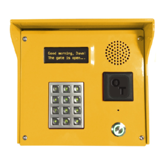
CIA-575-001 Rev 1.0 INSTALLATION General: The keypad is designed to request access to or from a secured area. It operates in conjunction with a controller that contains the list of access codes and areas these codes are valid for. The controller communicates with a master database that exists centrally accessible via the internet. - Page 5 CIA-575-001 Rev 1.0 from the edge. Also from the inside seal around each screw hole and the wire entry hole with an outdoor silicone sealant after pulling the wires through. Figure 2 – Mounting Template 3. Pull the necessary wires through the wire hole on the back of the housing. Allow ample wire to remain inside the housing.
-
Page 6: Wiring Connections
CIA-575-001 Rev 1.0 Wiring Connections: Below is a connection diagram for the Keypad PCBA Note: All installations must conform to local building and electrical codes and shall be in accordance with the Nation Electric Code, ANSI/NFPA 70 . When discrepancies exist between local codes and this manual, local code takes precedence. -
Page 7: Pwr/Rs485
CIA-575-001 Rev 1.0 PWR/RS485: Power and RS485 data communication is done with a single connector and should be the last connector to be attached as it may carry active power. We recommend that power and RS485 data communications be via a single 18 AWG, 4-conductor shielded cable. The shield drain wire can be used as the EARTH common wire. -
Page 8: Relay Outputs
CIA-575-001 Rev 1.0 Relay Outputs: Each relay has a Normally Closed (NC), a Common and a Normally Open (NO) connection. Depending on the need, wire to the common and either the NC or NO. On board LED’s are provided to show if the relay is activated. -
Page 9: Testing / Troubleshooting The Keypad
CIA-575-001 Rev 1.0 Testing / Troubleshooting the Keypad Test the keypad by applying power to the PWR/RS485 connections. An “Offline” message will initially be displayed after power is applied. Once the controller recognizes the device a standard welcome message will appear. There are also multiple LEDs as shown below that should be active as described for troubleshooting purposes. -
Page 10: Accessing The Display Pcb And Push Button Sub-Assembly's
CIA-575-001 Rev 1.0 Accessing the Display PCB and Push Button Sub-assembly’s: The main PCB is mounted on hinged standoffs. Loosening 4 thumb screws allows the PCB to be folded back in place to access the Display PCB and the metal push button assembly. Figure 6 The push button assembly is a single part held in place by 4 nuts in the 4 corners of the unit. -
Page 11: Keypad Maintenance
CIA-575-001 Rev 1.0 KEYPAD MAINTENANCE Cleaning the Housing and Touchpad Monthly: Inspect and clean the housing and touchpad on a regular basis (monthly) . To clean spray the unit with a mild soapy water solution then wipe it with a soft cloth. Do not use alcohol, harsh chemicals, abrasives, or petroleum-based products.
Need help?
Do you have a question about the INSOMNIAC CIA K-500 and is the answer not in the manual?
Questions and answers