Table of Contents
Advertisement
Quick Links
Advertisement
Table of Contents

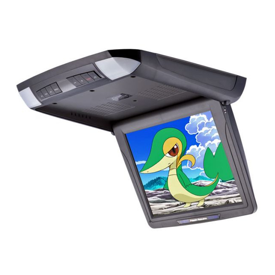
Summary of Contents for Power Acoustik PT-120CM
- Page 1 PT-120CM 12.1 Universal Ceiling Mount Monitor OWNER S MANUAL...
-
Page 3: Table Of Contents
CONTENTS Please read this User s Manual in detail and use the set properly. CAUTION INSTALLATION NAME AND FUNCTION OF EACH PART Unit Remote Control PICTURE CONTROL CONNECTIONS HOW TO OPERATION THE MONITOR Releasing The Monitor How To Watch Monitor SPECIFICATIONS... -
Page 4: Caution
CAUTION Please read and observe all warnings and instructions in this owner s manual and those marked on the unit. Retain this booklet for future reference. There are two kinds of alarm symbols as follows: The lightening flash with arrowhead symbol within an equilateral triangle is intended to alert the user to the presence of dangerous voltage within the product s enclosure that may be of sufficient magnitude to constitute a risk of electric shock to... -
Page 5: Specifications
SPECIFICATIONS Power Requirements D C 1 2 V Power Consumption Screen Size 1 2 . 1 T F T- L C D Screen Format 4 : 3 Resolution Pixel 2 4 0 0 x 6 0 0 A/V Inputs 2 A / V R C A I n p u t s Dimensions( With shroud) 1 5 . -
Page 6: Releasing The Monitor
INSTALLATION 1. Open the package and check that these items are presents. INSTALLATION PLATE UNIT 2. Connect the external compoments to the RCA cable or AV output. (Refer to the connection diagram on page 9) 3.Match the position of installation bracket and installation plate with screw A. -
Page 7: Name And Function Of Each Part
CONNECTIONS Red AUDIO(R) White AUDIO(L) DVD/VCD/CD/CD-R/CD-RW/MP3 Reset PLAY/PAUSE PREV NEXT STOP REMOTE EJECT POWER A/V INPUT Yellow VIDEO YELLOW AV Input + 12 V DC Battery (AV 2) BLACK Chassis Ground Door Trigger WHITE Trigger Door NAME AND FUNCTION OF EACH PART Red AUDIO(R) White AUDIO(L) DVD/VCD/CD/CD-R/CD-RW/MP3... -
Page 8: Remote Control
NAME AND FUNCTION OF EACH PART OSD MENU EXIT Button MENU Button MENU EXIT Dome Light Button AV Select Button +/- Buttons Interface Switch Function Power Power ON/OFF Signal Select Menu Press this button for OSD menu. And select menu option Increase current option value.


Need help?
Do you have a question about the PT-120CM and is the answer not in the manual?
Questions and answers