Advertisement
Quick Links
Advertisement

Related Manuals for Diagraph LA/4700

Summary of Contents for Diagraph LA/4700
- Page 1 4700-010 Revision B...
- Page 2 Diagraph has made every effort to verify the informa- tion contained in this manual, but reserves the right to correct any error at the time of the manual’s next revision.
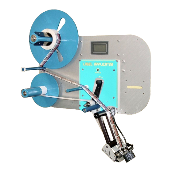
- Page 3 1.0 Introduction The LA/4700 Label Applicators The LA/4700 is a second generation, next label out, labeling system designed for modularity, continuous labeling, self-diagnostics, and ease of use. Modularity of design provides the basis for ease of installation, setup, and maintenance. The electronics system employs a hardware- specific design, thus increasing reliability and throughput.
-
Page 4: Document Conventions
Warranty Information The LA/4700 systems, including all components unless otherwise specified, carry a limited warranty. For all warranty terms and conditions, contact Diagraph, an ITW Company, for a complete copy of the Limited Warranty Statement. Introduction Page 3... -
Page 5: Specifications
Diagraph - an ITW Company LA/4700 User Manual - Revision B Specifications General Specifications Category Parameter 79 cm 58.5 cm Dimensions 31 in. ( ) L x 23 in. ( ) H x 63.5 cm (with Yoke) 25 in. ( 38.5 kg... - Page 6 Diagraph - an ITW Company LA/4700 User Manual - Revision B Mechanical Specifications - Pneumatic Systems Category Nominal Minimum Maximum Incoming Air Pressure 60 - 100 PSI 40 PSI 125 PSI Tamp Cylinder Pressure 30 - 50 PSI 20 PSI...
- Page 7 Diagraph - an ITW Company LA/4700 User Manual - Revision B 2.0 System Modules Drive Module Drive Module P/N: 4700-800 (W/T)(5/9)(R/L) The drive module contains all of the necessary equipment to perform the feeding and peeling of the label. The module is available in eight (8) different configurations listed below: P/N: 4700-800W5L Narrow Web WIPE -Left Hand P/N: 4700-800W5R Narrow Web WIPE -Right Hand P/N: 4700-800W9L Wide Web WIPE -Left Hand...
- Page 8 Diagraph - an ITW Company LA/4700 User Manual - Revision B Drive Roller P/N: 4700-630 (W) The drive roller is a subcomponent of the Servo Assembly. This roller is made of polyurethane and is responsible for advancing the label liner through the ...
- Page 9 Diagraph - an ITW Company LA/4700 User Manual - Revision B Tamp Peel Blade Assembly P/N: 4700-951 (W) The tamp peel blade assembly is used for tamp‐on, blow‐on, WASA, and FASA applications. It contains the label gap sensor, peel blade support, and peel blade. There are two versions of this assembly: • 5 inch wide, P/N: 4700‐951 • 9 inch wide, P/N: 4700‐951W Optional Photo Speed Encoder P/N: 4700-907 [kit] The Photo Speed Encoder or “Photocoder” is ...
- Page 10 Diagraph - an ITW Company LA/4700 User Manual - Revision B Mechanical SubSystem Unwind P/N: 4600-605 The unwind is designed to capture supply rolls up to 12 inches in diameter, with 3 inch cores. This subsystem uses a hub‐based fin design to capture the supply roll without need for an outer disk. This reduces ...
- Page 11 LA/4700 User Manual - Revision B Stand P/N: 6160-329 The stand holds the yoke assembly of the LA/4700 and allows the system to be orientated in a variety of positions to suit application requirements. The stand employs a hand crank to set vertical position, and a ...
- Page 12 Diagraph - an ITW Company LA/4700 User Manual - Revision B Inlet Filter/Regulator/Shutoff P/N: 4600-705 The inlet air filtration provides an OSHA‐ approved shutoff, with lock‐out, and a pressure regulator. It uses a 5 micron filter element and automatically purges ...
- Page 13 Diagraph - an ITW Company LA/4700 User Manual - Revision B Rewind Motor P/N: 4600-503 The rewind is designed around a brushless DC motor which uses three coils activated in sequence, according to three Hall‐effect sensors. This is an inherently closed‐loop motor control since the motor’s magnetic ...
- Page 14 Diagraph - an ITW Company LA/4700 User Manual - Revision B Product Sensor P/N: 4600-900 The product sensor is an infrared, diffused light model, capable of sensing objects at distances up to 3 ft. (900 mm). The sensor has two LED’s, one is a yellow detection indicator and the other serves two purposes. If no object is currently detected, the green ...
- Page 15 Diagraph - an ITW Company LA/4700 User Manual - Revision B Pressure Sensor P/N: 4600-905 The pressure sensor has several great features, and still maintains a simplicity in design. The sensor should not require adjustments since the threshold levels are set at the factory. The sensor constantly monitors pressure and triggers an error on the system if the air pressure drops below the ...
- Page 16 LA/4700 User Manual - Revision B 3.0 Configuration Identity The LA/4700 shares the same platform as the other Platinum Series units. This allows systems in the Platinum Series to share optional modules, applicator modules, and features which adds a great deal of diversity to the product line. In this simplification, the same MCU firmware and GUI memory run both the Printer-Applicators (PA/4600, PA/6000) and the Label-Applicator (LA/ 4700).
- Page 17 WASA Goal: Determine the best machine orientation for application. The LA/4700 are capable of rotating and pitching about various axes to accommodate a wide range of label placement opportunities. Select the best orientation from the given measurements and desired label locations.
- Page 18 FASA Goal: Determine the best machine orientation for application. The LA/4700 are capable of rotating and pitching about various axes to accommodate a wide range of label placement opportunities. Select the best orientation from the given measurements and desired label locations.
- Page 19 Diagraph - an ITW Company LA/4700 User Manual - Revision B Step 2 - Connect AC Power Goal: Connect the power supply to a noise-free AC power line. Note: When connecting the AC power outlet, do not use extension cords to power the unit.
- Page 20 Diagraph - an ITW Company LA/4700 User Manual - Revision B TAMP ** Step 3 - Connect Compressed Air FASA Goal: Provide the unit with clean, dry compressed air (Tamp and FASA applicator modules only) and connect the power supply to a noise-free AC power line.
- Page 21 Diagraph - an ITW Company LA/4700 User Manual - Revision B Step 4 - Mount and Adjust the Product Detector Goal: Determine which mounting location is ideal, either on the baseplate, on the snorkel, or on the conveyor system. Goal: Adjust the sensor to detect just the product, and ignore background objects, such as forklift trucks, personnel, or other objects that may pass in front of the sensor’s view.
- Page 22 Diagraph - an ITW Company LA/4700 User Manual - Revision B Step 5 - Configure the One Time Settings (OTS) Goal: Enter the One Time Settings screens and select the configuration of this particular system. Note: Most of these items were determined when the unit was assembled; so only configurations that have changed require this adjustment.
- Page 23 Diagraph - an ITW Company LA/4700 User Manual - Revision B Step 7 - Enter Values for the Job Settings Goal: Enter Job setting values to control specific aspects of the product label application Map: Beginning in the Offline mode, press the Settings button. From the Settings Menu, which...
- Page 24 Diagraph - an ITW Company LA/4700 User Manual - Revision B TAMP ** Step 8 - Adjust the Inlet Filter / Regulator FASA Goal: Apply air to the system, adjust the incoming regulator, and verify air quality Be certain that nothing is going to interfere with the cylinder extending or retracting, and apply air line pressure to the system by switching on the OSHA-approved shutoff switch on the inlet filter/regulator.
- Page 25 Diagraph - an ITW Company LA/4700 User Manual - Revision B ** Step 10 - Load the Media WIPE Goal: Correctly load the label supply and web the applicator. LABEL SUPPLY CHANGEOUT Begin by removing the last supply roll core and remaining label liner from the system. Insert the new roll over the unwind fins and press roll firmly against the unwind disk (A).
- Page 26 Diagraph - an ITW Company LA/4700 User Manual - Revision B TAMP ** Step 10 - Load the Media FASA WASA Goal: Correctly load the label supply and web the applicator. LABEL SUPPLY CHANGEOUT Begin by removing the last supply roll core and remaining label liner from the system.
- Page 27 Diagraph - an ITW Company LA/4700 User Manual - Revision B ** Step 11 - Adjust the Wipe-On Snorkel WIPE Goal: Adjust the wipe-on angle of the label and set the optimum brush position. •••• Sub-Step (a) •••• [1] Use a...
- Page 28 Diagraph - an ITW Company LA/4700 User Manual - Revision B ** Step 11 - TAMP Adjust the Tamp Pad Position FASA Goal: Slide the tamp cylinder module across the dovetail track to the correct position in front of the drive module, this will be approximately 1/8th of an inch from the peel blade edge.
- Page 29 Diagraph - an ITW Company LA/4700 User Manual - Revision B ** Step 12 - TAMP Set the Tamp Pneumatic Controls FASA Goal: Adjust the optimum tamp pad travel to ensure label transfer to the product These adjustments will require an initial setup and a final adjustment, as other parameters are changed.
- Page 30 Diagraph - an ITW Company LA/4700 User Manual - Revision B TAMP ** Step 13 - Set the Vacuum, Air, and Blow Values FASA Goal: Set the air assist flow control, vacuum and blow pressure, and blow flow control. •••• Sub-Step (a) ••••...
- Page 31 Diagraph - an ITW Company LA/4700 User Manual - Revision B Step 14 - Calibrate Label and Test Cycle Goal: Calibrate the label gap sensor for the material used and test cycle the system. •••• Sub-Step (a) •••• [1] Press the “Label” menu from the Offline Home Screen.
- Page 32 Diagraph - an ITW Company LA/4700 User Manual - Revision B TAMP Step 15 - Test Tamp FASA Goal: Make fine adjustments to optimize the performance of the system once running. •••• Sub-Step (a) •••• Tamp Duration (2nd Tamp Duration)
- Page 33 Diagraph - an ITW Company LA/4700 User Manual - Revision B Step 16 - Make Final Adjustments Goal: Make fine adjustments to optimize the performance of the system once running •••• Sub-Step (a) •••• Product Delay (Second Product Delay) The product delay controls the time between the product detector trigger and start of the application cycle.
-
Page 34: User Interface
Diagraph - an ITW Company LA/4700 User Manual - Revision B 5.0 User Interface One Time Setting (OTS) Screens Map: Power On Note: Can only be entered from power on transition Screen Functionality If the Label Present sensor is installed on the unit, press the button below the text until it displays “Yes”. - Page 35 Diagraph - an ITW Company LA/4700 User Manual - Revision B Screen Functionality The Label Shape has two choices of Normal and Irregular. Normal should be used for rectangular opaque labels and Irregular should be used for round or non-rectangular shaped labels or when a registry mark (black mark) is used for clear labels.
- Page 36 Diagraph - an ITW Company LA/4700 User Manual - Revision B System Settings Screens Map: Screen Functionality The system can be selected to Tamp, Tamp/Blow, or Blow. In addition, there are selections for having a double apply for applications such as Front Apply Swing Arms (FASA) or two labels per product.
- Page 37 Diagraph - an ITW Company LA/4700 User Manual - Revision B Job Settings Screens Map: Note: Can only be entered from an offline state Screen Functionality ALL APPLY MODES From this screen the user can switch jobs, thus recalling multiple job settings at once.
- Page 38 Diagraph - an ITW Company LA/4700 User Manual - Revision B Screen Functionality DUAL APPLY MODES page 35 Only displayed if the system Apply Mode ( ) is set to 2 Tamps, 2 Tamp/Blows, or 2 Blows. Calculated the same as above, but with extra time to allow the second label to feed and be ready for the second application.
- Page 39 Diagraph - an ITW Company LA/4700 User Manual - Revision B Screen Functionality ALL APPLY MODES In this screen, the trigger for feeding the next label is selected. For batch applications requiring the fastest throughput, the choice of Tamp Return works best. This will dispense a label each time the tamp pad returns home.
- Page 40 Diagraph - an ITW Company LA/4700 User Manual - Revision B Diagnostic Screens Map: Screen Functionality From the main Diagnostics screen, the individual categories of Options, Rewind, Drive Module, Sensors, and Pneumatics can be tested. Once the Diagnostic menu is entered, the warning tower and discrete outputs will begin to toggle automatically to test these outputs.
- Page 41 Diagraph - an ITW Company LA/4700 User Manual - Revision B Screen Functionality The Sensor Diagnostic screen shows all of the main system sensors on one screen. An indicator with a black background is active, while a white background indicates inactive. The sensor names are limited to three characters, with the meanings listed here: •...
- Page 42 Diagraph - an ITW Company LA/4700 User Manual - Revision B Discrete I/O Map: Note: This only applies to units equipped with the optional 6145-405 Discrete I/O Kit Screen Functionality Use this menu to map the desired output event to the output port number.
- Page 43 Diagraph - an ITW Company LA/4700 User Manual - Revision B Screen Functionality Use this menu to map the desired input event to the input port number. The selection choices are identical for each of the inputs 1 through 4 (Input 1 shown at left).
- Page 44 Diagraph - an ITW Company LA/4700 User Manual - Revision B Information Screens Map: Note: Information screens can be entered while running (online) or offline. The below columns indicate the menu structure for the given information area: Web Path System...
- Page 45 Diagraph - an ITW Company LA/4700 User Manual - Revision B Power On/Off Screens Map: Screen Functionality By pressing the Enter Standby button the unit goes offline and devices on the switched 24 VDC supply are turned off. Once off, the screen will transition to the next following screen for turning it back on.
-
Page 46: Troubleshooting
Diagraph - an ITW Company LA/4700 User Manual - Revision B 6.0 Troubleshooting System Warnings Note: Any of the following warnings will be displayed on the screen, and the system will continue operation. This line will change as the status or warning is... - Page 47 Diagraph - an ITW Company LA/4700 User Manual - Revision B System Errors Note: Any of the following errors will place the unit in offline, thus stopping operation Screen Screen Screen E02 ‐ Repeat Label Cycle E03 ‐ Repeat Tamp Cycle E04 ‐ Cylinder Not Home E06 ‐ Air Pressure Out E07 ‐ Rewind Tension E08 ‐ Label Supply Out E09 ‐ Second Apply Error E10 ‐ External Input E11 ‐ Drive Module...
- Page 48 Diagraph - an ITW Company LA/4700 User Manual - Revision B Electrical Test Points Power Supply Terminals Measure these tests with a VOLT-METER and the cables disconnected from the pc board Test Expected Result • +V to ‐V 48 VDC +/‐ 0.5 VDC • N to L 100‐240 VAC...
- Page 49 Diagraph - an ITW Company LA/4700 User Manual - Revision B Servo Controller Board (4700-350) Test Points WARNING These measurements must be taken with the top cover removed, where High-Current DC voltages are present. Please use caution when measuring test point voltages and never attempt to disconnect cabling while the unit is powered on.
- Page 50 Diagraph - an ITW Company LA/4700 User Manual - Revision B Rewind & Servo Motor Measure these tests with an OHM-METER and the cables disconnected from the pc board. Test Expected Result • Coil A to Coil B Less than 2 Ω • Coil B to Coil C Less than 2 Ω • Coil C to Coil A Less than 2 Ω...
- Page 51 Diagraph - an ITW Company LA/4700 User Manual - Revision B Problem - Solution Matrix COMMON TO ALL SYSTEMS (Check these first before proceeding to specific system type) Problem Cause Correction Multiple labels are fed, without Label gap sensor is not Perform the calibration a pause between labels calibrated procedure for setting the label page 30 gap sensor level. See ...
- Page 52 Diagraph - an ITW Company LA/4700 User Manual - Revision B WIPE SYSTEMS Problem Cause Correction Unit will not dispense a label Unit is offline or has an error Press run button to place unit when product detector is condition online, if no errors exist. If triggered errors exist, determine error type from the display and clear error condition. Attempt to go online by pressing the run button (this will also check for remaining errors). Cabling problem Test product detection through page 40 diagnostics on Labels are wrinkled (or Dispense speed too high Reduce Dispense Speed page 36 crumpled) on the product Peel blade angle is not correct...
- Page 53 Diagraph - an ITW Company LA/4700 User Manual - Revision B TAMP SYSTEMS Problem Cause Correction page 40 Label is on the tamp pad, but Product detector not triggered Verify in Diagnostics ( ) tamp cylinder does not fire by product that the product detector can repeatedly detect the product. Adjust sensor as necessary Apply trigger occurred before Increase distance of product label was on tamp pad detector from tamp pad to allow feeding to complete Tamp pad is contacting product Auto‐Retract delay time is too Decrease the Auto‐Retract delay with too much force or for too long time to start the cylinder return long a duration sooner.
- Page 54 Diagraph - an ITW Company LA/4700 User Manual - Revision B Problem Cause Correction Labels are feeding into the edge Tamp pad position too low Set tamp pad to a distance just of the tamp pad. below the peel blade. See Tamp Cylinder Adjustments on page 27 Cylinder home sensor position Move the cylinder home sensor too low to a position where the cylinder is detected home later. Air cushion set too slow The air cushion slows cylinder travel at the return position. Too much cushion cause reduce speed at the home position. Set cushion at optimal position between slow return and end of page 28 travel contact. See Troubleshooting Page 53...
- Page 55 Diagraph - an ITW Company LA/4700 User Manual - Revision B Catch Problems Before They Cause Downtime Air Volume (CFM) Problems Air pressure is the main consideration when connecting a machine requiring compressed air, but air volume (measured in cubic feet per minute) is just as important for regular operation. An elec- trical analogy would be: the air pressure can be thought of as voltage and the air volume can be thought of as electrical current.
-
Page 56: Maintenance Schedule
This is a simple process of using a software application named MTool2. This can be located on the Diagraph web site, under downloads. To perform a firmware upgrade, download the MTool2 and fill out the form to request an access license. - Page 57 Diagraph - an ITW Company LA/4700 User Manual - Revision B Parts List Part Number Description Recommende d Spare Part DOCUMENTATION 4700‐010 LA/4700 User Manual 4600‐015 Service Tool Software LA/4700 DRIVE MODULE 4700‐500 Servo Assembly Narrow Web (Either Handed (R & 4700‐500W Servo Assembly Wide Web (Either Handed (R & L) 4700‐630...
- Page 58 Diagraph - an ITW Company LA/4700 User Manual - Revision B Part Number Description Recommende d Spare Part TAMP PEEL BLADE ASSY. Narrow and Wide Versions Contain: • Peel Blade Support • Peel Blade • Hold‐Down Plate • End Plate • Gap Sensor 4700‐951 Tamp Peel Blade Assembly ‐ Narrow Web (L&R) 4700‐951W Tamp Peel Blade Assembly ‐ Wide Web (L&R) LA/4700 SYSTEM 4700‐950 LA/4700 Wear‐Items Maintenance Kit 4600‐522 Power Supply 4600‐643...
- Page 59 Diagraph - an ITW Company LA/4700 User Manual - Revision B Part Number Description Recommende d Spare Part 4600‐903 (old‐style flat window) Auto‐retract, Label low, or Label present sensor 6000‐903 (new‐style sphere window) and PUR cable (1 sensor/cable/cover per kit) 6000‐420 Ethernet Module (Wired and Wireless) 4700‐907 Photo Speed Encoder Linespeed Sensing Kit 4700‐908 Clear Label Sensing Kit Maintenance Page 58...
- Page 60 Diagraph - an ITW Company LA/4700 User Manual - Revision B Assembly Views and Part Numbers Maintenance Page 59...
- Page 61 Diagraph - an ITW Company LA/4700 User Manual - Revision B Maintenance Page 60...
- Page 62 Diagraph - an ITW Company LA/4700 User Manual - Revision B Maintenance Page 61...
- Page 63 Diagraph - an ITW Company LA/4700 User Manual - Revision B Maintenance Page 62...
- Page 64 Diagraph - an ITW Company LA/4700 User Manual - Revision B 8.0 Connection Port Information Product Detector J2, J3 DB9 Female Pin Description Pins 1, 2 Pin 3 Ground Pins 4, 5 Pin 6 +24 VDC Supply Pin 7 Pin 8 Product Detector Input Pin 9 Auxiliary Port Pin-Out J4 DB9 Male Pin Description Pin 1,2 Pin 3...
- Page 65 Diagraph - an ITW Company LA/4700 User Manual - Revision B Warning Tower Pin-Out J4 DB9 Female Pin Description Pin 1, 2, 3 Pin 4 Red (Ground Switched) Pin 5 Yellow (Ground Switched) Pin 6 + 24 VDC Supply Pin 7 Green (Ground Switched) Pin 8,9 Serial Communication Pin-Out J1 DB25 Female Pin Description Pin 1 Shield Ground Pin 2 Receive Pin 3 Transmit Pin 4...
- Page 66 Use arrow buttons (A) for increasing and (B) for decreasing the set-point. The default setting should be 60 PSI for operation with the LA/4700 unit. Press the Edit button until the sensor returns to the main screen.
- Page 67 Diagraph - an ITW Company LA/4700 User Manual - Revision B 10.0 Declaration of Conformity DECLARATION OF CONFORMITY Diagraph, an ITW Company, hereby declares that the equipment specified below has been tested and found compliant to the following directives and standards- Directives: Standards: •...
- Page 68 Diagraph - an ITW Company LA/4700 User Manual - Revision B 11.0 System Configuration Notes Setting Value Model Application Method Wipe Tamp FASA WASA Other OTS (One Time Settings) Label Present Installed Yes Auto Retract Installed Yes Label Low Installed Unit Configuration Left‐Hand Right‐Hand Missing Label Warning Error Label Shape...
- Page 69 Diagraph - an ITW Company LA/4700 User Manual - Revision B Setting Value DISCRETE I/O Input 1 None Online Prod Det 1 Prod Det 2 Error Input 2 None Online Prod Det 1 Prod Det 2 Error Input 3 None Online Prod Det 1 Prod Det 2 Error Input 4 None Online Prod Det 1 Prod Det 2 Error Output 1 ____________________________ Output 2...
Need help?
Do you have a question about the LA/4700 and is the answer not in the manual?
Questions and answers