Table of Contents
Advertisement
Quick Links
Advertisement
Table of Contents

Related Manuals for Carbest SNIPE


Summary of Contents for Carbest SNIPE
- Page 2 GPS LED confirm the current location from 24 numbers of GPS satellite in the world . When your SNIPE identify GPS signal, GPS LED light will be solid on, no matter antenna is pausing or moving. GPS helps better able to searching satellite faster & catch “GPS”...
- Page 3 When the satellite LED light is start to flashing, wait until it become solid on. When the satellite LED light become solid on, watch the satellite TV!! WARNING When you move SNIPE, make sure the position of antenna should be in Home position. NOTE Purchase Power Adapter separately from us, or if you purchase it on your own, purchase ONLY 18V / 3.3A which is certified.
- Page 4 4. Program update 4-1. Connection Diagram for updating “USB port is used for firmware upgrades only” MAIN UNIT Controller CONTROLLER B type Adaptor or Cigar jack USB cable A type Simply connect the Controller to PC using USB cable. USB cable is not included in the package.
- Page 5 4-2. Update Process Using SNIPE Update Program, refresh the satellite data of your SNIPE. Update the 9 satellites which are pre-stored. ① Download the SNIPE Update Program to your PC from our homepage (www.i-do-it.co.kr). ② Download the newest satellite data to your PC from our homepage.
- Page 6 ⑥ When folder is opened, select file and click the “OPEN” button. ⑦ The data of 9 satellites are not shown to you, as it will not be fixed by yourself.
- Page 7 ⑧ Check the Port Setting, which one opened, then click the “OPEN” button. ⑨ Once “SEND” button is activated, click the “SEND” button. ⑩ Wait until green bar reaches to the end.
- Page 8 ⑪ Once green bar reaches to the end and shows “SEND OK” massage, update is completed. Update USER 1, 2, 3 ① USER 1, 2, 3 are for extra addition of your desired satellites which are not pre-stored, and the way to add is almost same as above.
- Page 9 Satellite signals can be blocked or degraded by buildings, trees. Make sure there are no obstructions in a southward direction. ii. Check your program of Controller often, and get the latest updates for your SNIPE C. Mechanical problems In case of the antenna does not move at certain position.
-
Page 10: Specifications
6. Specifications 6-1. Dimension MAX 422mm MIN 188mm 188mm 126mm 454mm 316mm 6-2. Specification Dimensions 454 x 316 x 188 mm Main Unit / Full Package(Portable) / Weight 10Kg / 15.6Kg / 16.9Kg Full Package(Camping car Installation) Work Condition Stationary Antenna Gain 33.7 dBi @ 12.7GHz Min EIRP... -
Page 11: Table Of Contents
Contents 1. General Information 1-1. Introduction ..................1-2. -
Page 12: General Information
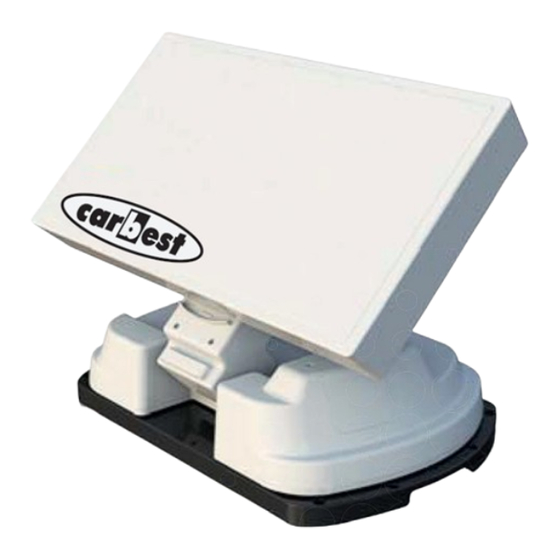
Thanks to its innovative technology, SNIPE is easy to mount on almost any motor vehicle. The SNIPE only occupies requisite space while it performs the necessary adjustments with the slim and agile antenna body For general operation, please ensure that the system always has a clear view to the south. -
Page 13: Proper Use And Operation
1-2. Proper use and operation This product has been designed for use in a portable use and fixed installation on vehicles with maximum speeds of 130 km/h. It is designed to automatically aim an antenna at geostationary television satellites transmitting directly to Europe. The power to the system is supplied by a standard vehicle electric system with a rated voltage of 12 or 24 Volts. -
Page 14: Safety Notes
1-3. Safety Notes In order to ensure that your SNIPE works properly, you must ensure that it is correctly connected follow the Operating Instructions in this manual. When it is correctly installed, the antenna automatically assumes the rest position when the ignition is switched on and locks itself there. -
Page 15: Accessory Include
2. Contents 2-1. Accessory Include Receiver cable Main unit Controller Controller bracket (12m – Grey color) Controller cable User manual Carrying case (12m – Black color) camping accessory Option Adaptor Cable holder Cable gland Cable gland rubber Cigar jack Allen wrench Mounting plate M6 ×... -
Page 16: Name Of Parts
2-2. Name of parts Main unit Skew pivot : -60° ~ +60° Elevation : 15° ~ 90° Main body : 360° turning Mounting plate : Shock-absorbing sponge Camping car installation Sustain body to Receiver to Controller Controller GPS state light Power switch HOME state light Bracket... -
Page 17: Connection Diagram
3. Operating Instruction 3-1. Connection Diagram MAIN UNIT RECEIVER Recever cable (Grey color) Controller CONTROLLER Adaptor or Cigar jack Using black color of controller cable, connect between controller and antenna. The controller cable looks same as the antenna cable, that please make sure distinguish them by the color and labeling of the cables. -
Page 18: Functional Description
3-2. Functional Description A. Power On Function Description Operation When the all cable connections are completed, switch on “Power” Switch with the “Power Switch” button on the top of the controller. If the position of antenna was in home position, “Home “Home State”...
Need help?
Do you have a question about the SNIPE and is the answer not in the manual?
Questions and answers