
Summary of Contents for Solcon TPR-6
- Page 1 Ver. June 1 2010...
-
Page 2: Table Of Contents
8.1 Dismantling the Main PCB and the Input PCB ............... 21 Tripping / Alarm Default Settings ..................22 Flash Messages ........................23 TPR-6 Communication ......................24 Technical Specifications ..................... 25 Dimensions and Cut-Out Dimensions ................26 Ordering Information ......................27 Notes ............................ -
Page 3: Introduction
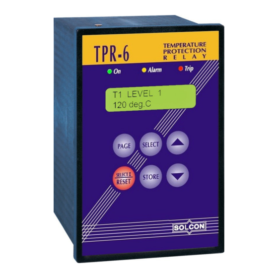
The TPR-6, Temperature Protection Relay is a new generation of micro-processor based relay, designed to protect electric motors, transformers and other systems from over temperature. The TPR-6 has 6 or 14 temperature inputs that can be programmed to measure Thermistors (PTC or NTC) and RTDs (Pt100). - Page 4 Parameter setting through the serial link may be easily disabled through manual keypad setting. Up to 32 TPR-6 units can be connected on the same link to the host computer. ________________________________________________________________________________________________...
-
Page 5: Wiring Diagram
5 • Wiring Diagram WIRING DIAGRAM Notes: 1. ALARM RELAY A can be programmed as ALARM or ALARM FAIL SAFE (default setting) or TRIPPING/ALARM. TRIP RELAY B can be programmed as TRIP (default setting) or TRIP FAIL SAFE or TRIPPING/ALARM. Refer to section 6 .2 Parameter Setting –... -
Page 6: Terminals Review
110-240V 50/60Hz or DC (+10% / -15%) Phase/Positive Lead ........Neutral/Negative Lead ......... Ground ............The TPR-6 incorporates four relays, each with 1-C/O contact, rated 8A/250 VAC, 2000VA resistive. See I/O SETTINGS (page 2). Note: Tighten terminals 18, 19, 20 to 7 in-lbs... - Page 7 7 • Terminals Review Thermal Inputs The TPR-6 can accept inputs from the following types of thermal sensors: RTD - Platinum 100 Ohm (Pt100) - Three-wire measurement system to be used to compensate for cable resistance. Thermistors - field Programmable as PTC or NTC (Two wire) Notes: 1.
-
Page 8: Front Panel Description
8 • Front Panel Description FRONT PANEL DESCRIPTION LEDs On - Illuminates when auxiliary power supply voltage is connected. Alarm - Illuminates in Alarm condition. Stays lit even if alarm condition disappears, turns off after resetting. Trip - Illuminates in Trip condition. Stays lit even if trip condition disappears, turns off after resetting. -
Page 9: Mode Pages Display
9 • Mode Pages Display MODE PAGES DISPLAY Upon initiation the LCD will display: TEMPERATURE *** SETTINGS *** By pressing PAGE key the following pages can be reviewed I / O *** SETTINGS *** TRIPPING / ALARM *** OPTIONS *** ACTUAL DATA **** STATISTICAL DATA... -
Page 10: Parameter Setting - Temperature Settings
TYPE, T3 SENSOR TYPE .. etc. Important Note: In order to set the sensor type connected to the TPR-6 the Tx SENSOR TYPE parameter must be set accordingly and dip switch setting must be done as well. Refer to section 8 page 20 for ... - Page 11 11 • Mode Pages Display Press SELECT TEMP. LEVEL 2 DELY 2.0 SEC. Time delay for Level 2 (for all sensor channels) to set time delay Press ▲ or▼ keys Range: 0.1 – 20 Sec. Press SELECT Tx IN GROUP ? Any sensor 1-14 can be grouped for group measurement and analogue output.
-
Page 12: Parameter Setting - I/O Settings
12 • Mode Pages Display Parameter Setting – I/O Settings I / O *** SETINGS ***. Press SELECT CONFIG. ALARM REL ALARM FAIL SAFE Configure Alarm Relay function Press ▲ or▼ keys to set required operation mode Range: ALARM, ALARM FAIL SAFE, TRIPPING/ALARM ALARM - the relay changes position upon trip and returns to original position upon reset, after fault has been removed. - Page 13 13 • Mode Pages Display Press SELECT AN. OUT PARAMETER GROUP MAXIMUM Configure Analogue Output – related to the minimum, average or maximum of the selected group Range: GROUP MINIMUM, GROUP AVERAGE, GROUP MAXIMUM, T1, T2,T3..R1, R2..Press SELECT AN. OUT FUL RANGE 200 deg C Analogue Output Full Range Press ▲...
-
Page 14: Parameter Setting - Tripping And Alarm Options
TRIPPING/ALARM OPTIONS mode page. Protection function Each of the TPR-6 Protections can be assigned to each of the following functions : 1. TRIP function – ENABLED or DISABLED, if ENABLED can be programmed to TRIP or TRIP-FAIL SAFE function (see I/O SETTINGS page) 2. - Page 15 TRIP the unit. 13 - CONFIG. INPUT 1 is set as EXTERNAL Range DISABLE, ENABLE FAULT 1 NC and the TPR-6 detects open circuit between terminal 13 terminal 15 Press SELECT to see ALARM, AUTO RST, RELAY (common) input terminals.
- Page 16 COMM PORT FAILED TRIP: DISABLED Fault occurs when the TPR-6 detects three consecutive transmissions from the host computer, in which a parity bit, and/or the CRC word are wrong. Enabling, Disabling trip function upon communication failure. Press ▲ or▼ keys to set this function.
-
Page 17: Actual Data
17 • Mode Pages Display Actual Data ACTUAL DATA - **** - The following demonstrates the readings with the following settings in TEMPERATURE SETTINGS: T1 SENSOR TYPE is set to RTD T2 SENSOR TYPE is set to PTC THERMISTOR T3 SENSOR TYPE is set to PTC THERMISTOR Press SELECT T1 TEMPERATURE 110 deg. -
Page 18: Statistical Data
R3 – MAX. VALUE 25.5 KOHM Press SELECT More than One Alarm or Trip. The TPR-6 is designed to accept and store the first LAST TRIP alarm it detects. If this alarm has not been reset and T1 LEVEL 1... -
Page 19: Service Mode
19 • Mode Pages Display Service Mode Press PAGE and ▼simultaneously, the following will display: *** SERVICE *** *** OPTIONS *** Press SELECT RUN SELF TEST ? PRESS “ VALUE-UP” If test was OK the display will show for a short time SELF TEST PASSED If test failed the display will show SELF TEST FAILED... -
Page 20: Resistance/Temperature Conversion Table Pt. 100 As Per Din 43760
DIP SWITCHES SETTINGS FOR PT100/THERMISTOR INPUTS DESIGNATION The following must be done in order to set the right sensors connected to the TPR-6: 1. Set the sensor type in the TEMPERATURE SETTINGS page. Refer to section 6 .1 page 10. -
Page 21: Dismantling The Main Pcb And The Input Pcb
Note: This procedure must be done by a qualified personnel. Verify that the TPR-6 is completely disconnected from any power source before this procedure is done. Identify the Main PCB (in All models) and Input PCB (TPR-6/14 only). 2. Remove four screws holding the back cover of the TPR-6 and remove the cover. -
Page 22: Tripping / Alarm Default Settings
General notes for future reference concerning this installation. Mark the newly programmed values into the parenthesis ( ) of each item for future reference. Installation Number : _________________, TPR-6 Serial Number : ________________________ Drawing Number : ______________________, Project Name/Number : _____________________ Protection... -
Page 23: Flash Messages
23 • Flash Messages FLASH MESSAGES The message is displayed for a short while only. Display than returns to the previous message. Flash messages are usually displayed as a response to an operator action. It is used either to confirm activation of the requested operation, or to indicate reason for not doing so. Flash messages are : Display Description... -
Page 24: Tpr-6 Communication
This communication system is unmatched in its reliability, flexibility and ease of use providing the ideal basis for the design of a modern motor management system. The TPR-6 incorporates RS485 serial link and uses a MODBUS RTU protocol (The protocol is not included in this document) to provides high speed data acquisition to supervisory computers. -
Page 25: Technical Specifications
Power consumption: 12 VA or 10W. Recommended fuse rating: 0.5A. Temperature Inputs Types: TPR-6/6 with 6 temp. inputs and TPR-6/14 with 14 temp. inputs Temp. Inputs: Field adjustable (dip switches) as RTD (Pt100) or Thermistors (software programmable as PTC or NTC). -
Page 26: Dimensions And Cut-Out Dimensions
26 • Dimensions and Cut-Out Dimensions DIMENSIONS AND CUT-OUT DIMENSIONS 86.4 Cut-Out ________________________________________________________________________________________________... -
Page 27: Ordering Information
27 • Ordering Information ORDERING INFORMATION TPR-6 No. of Supply Comm. Required Front Temp. Voltage Options Panel Inputs No. Of Temp. Inputs Specify Description 6 Temperature Inputs 14 Temperature Inputs Supply Voltage Specify Description 110-240V 50/60Hz or DC (+10% / -15%)
Need help?
Do you have a question about the TPR-6 and is the answer not in the manual?
Questions and answers