
Summary of Contents for Olympia LT-80
- Page 1 OLYMPIA BURNER OPERATING MANUAL MODEL: LT-40,45,60,80,100,120,150, 200,250,300,400,500,600,700 OLYMPIA INDUSTRIAL CO., LTD.
- Page 2 CONTENT 1. INTRODUCTION OF PRODUCT. 1) BURNER SPECIFICATION. 2) COMBUSTION PERFORMANCE GRAPH. 3) SIZE AND DIMENSION. 4) EXPLODED DRAWING OF BURNER AND PART NAME. 2. HOW TO CONTROL BURNER. 1) BURNER COMBUSTION FURNACE DIMENSION. 2) HOW TO INSTALL BURNER. 3) DIAGRAM OF FUEL CIRCULATION SYSTEM. 4) HOW TO INSTALL FUEL PIPE SYSTEM.
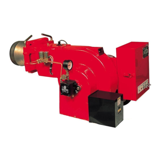
- Page 3 1. INTRODUCTION OF PRODUCT. LT-Series oil Burner is also designed and manufactured upon our well experienced technique and is made of motor, oil pump, fan, ignition equipment and automation in single body. the highly pressurized fuel particulates are perfected burnt, which minimizes smoke it has following benefits.
- Page 4 2)COMBUSTION PERFORMANCE GRAPH.
- Page 5 3) SIZE AND DIMENSION. ① LT-40,45,60 DIMENSION...
- Page 6 ② LT-80,100,150,200,250,300,400,500,600,700 DIMENSION ◉ LT-series burner is an hydraulic gun type burner with forced flue fan. the ignition rate is controlled as follows depending on the number of nozzle. ․ two nozzle: 2-position control( hi-low-off) ․ three nozzle: 3-position control(hi-mid-low-off) one proportional nozzle: proportional control(modulating) ◉...
- Page 7 4) EXPLODED DRAWING OF BURNER AND PART NAME. (1) LT-40U,45U,60U BURNER EXPLODED DRAWING.
- Page 8 (2) LT-40UH,45UH,60UH BURNER EXPLODED DRAWING.
- Page 9 (3) LT-80U,100U,150,200,250,300,400,500,600,700 BURNER EXPLODED DRAWING. * LT-80T,100T,150,200,250,300 = DAMPER MOTOR LT-250,300,400,500,600,700 = 3NOZZLE...
- Page 10 2. HOW TO CONTROL BURNER 1) BURNER COMBUSTION FURNACE DIMENSION MODEL LT-40 LT-45,60 LT-80,100 LT-150,200 LT-250,300 LT-400,500,600,700 2) HOW TO INSTALL BURNER. (1) burner assembly sequence(refer to above sketch) ① insert gasket into the burner hinge. insert burner to the boiler fire outlet or combustion furnace, and tightly fasten.
- Page 11 (2) caution during burner installation ① make it sure to install burner horizontally. ② fasten bolts tightly so that no combustion gas leaks. ③ after installing the hinge-type burner, use care so that no part of ignition bar is damaged or deformed during assembly of frame. ④...
- Page 12 4) HOW TO LAY FUEL PIPE the installation of the fuel pipe system for the gun type oil burner is divided into single type pipe installation using the height of oil tank and dual type pipe installation using sucking power of burner pump. ▶...
- Page 13 5) TIME CHART...
- Page 14 (6) ELECTRIC CIRCUIT DIAGRAM.
- Page 15 * MODURATING TYPE...
- Page 16 3. HOW TO USE MAJOR PARTS. 1) COMBUSTION HEAD DIMENSION. ◉ in case of adjusting "C" size, be careful not to touch the and of ignition bar with diffuser or diffuser is not stained with oil. 2) HOW TO ADJUST COMBUSTION AIR FLOW RATE. (1) hydraulic cylinder.
- Page 17 ② how to adjust first stage(low combustion) air adjustment : loosen the nut A, and adjust the damper opening B for normal combustion. then fully tighten the nut A. ⓑ second stage(high combustion) air adjustment : loosen the nut D in the high combustion mode, and tighten adjuster nut C to increase air flow rate until no smoke coming out from the chimney, when adjustment is over, fully tighten the nut D so that the adjuster nut is not loosened.
- Page 18 ② electric circuit diagram ③ how to adjustment damper damper gauge consists of from "0"to"10", "0" indicates complete close and "10"indicates complete open . ㉠ disconnect power. ㉡ adjust each CAM by deciding the position depending on the combustion rate.
- Page 19 ex) low combustion damper open : 2/10 open. medium combustion damper open : 4/10 open. high combustion damper open : 6/10 open. ⓐ see each CAM of the damper open scale. accord with marked CAM scale according to the setting position. ⓑ...
- Page 20 ◉ in the burner model LT40UH, LT45UH, LT60UH separate burner from the furnace. then also separate the flange tube, and follow the adove procedure for replacement. b) how to disassemble and check nozzle ① separate filter (㉣). clean the filter using kerosene. ②...
- Page 21 4) FLAME DETECTOR. ① flame detector detects igniting conditions of burner. when it detects that ignition fails, it stop burner operation as a safety device. ② when burner stops operation several seconds after burner ignitions, check whether there is a soot or dust on the flame sensor of the flame detector.
- Page 22 burner model LT-40U,40UH LT-45U~LT-200T LT-200M~LT-250M LT-250T~700T pump model AS&VM TYPE AJ TYPE E TYPE TA TYPE pump capacity(2850rpm)-ℓ/h 33~47 40~205 110~350 310~750 output pressure-bar 7~14 10~30 14~30 7~40 max. inlet pressure-bar max. return pressure-bar max. suction height-bar 0.45 0.45 0.45 0.45 max.
- Page 23 ☞ auction: take care of the ignition transformer as high voltage is applied to the ignition transformer. 7) FUEL FILTER. ▶ how to handle fuel filter ․ the fuel filter removes foreign substance from fuel. ․ when burner does not generate flame as no fuel is fed even if oil pipe is contained in the fuel tank, clean the fuel filter.
- Page 24 5. HOW TO MAINTAIN, CHECK AND SERVICE BURNER. 1) CHECK OF BURNER. ▶ check the followings prior to burner operation. ① after checking the water level of boiler, pressure and fuel feed rate, open the valve between tank and oil pump. ②...
- Page 25 2) BURNER TROUBLE/ACTION TABLE...
- Page 26 3) CAUSE OF TROUBLE AND COUNT-MEASURE ACTION trouble major cause action 1. flame sensor detects danger. ․ reset after removing signal, and stops operation. the cause of trouble. motor does not 2. protector relay is out of order. ․ replace and repair. operate.
Need help?
Do you have a question about the LT-80 and is the answer not in the manual?
Questions and answers