Advertisement
Available languages
Available languages
Table of Contents
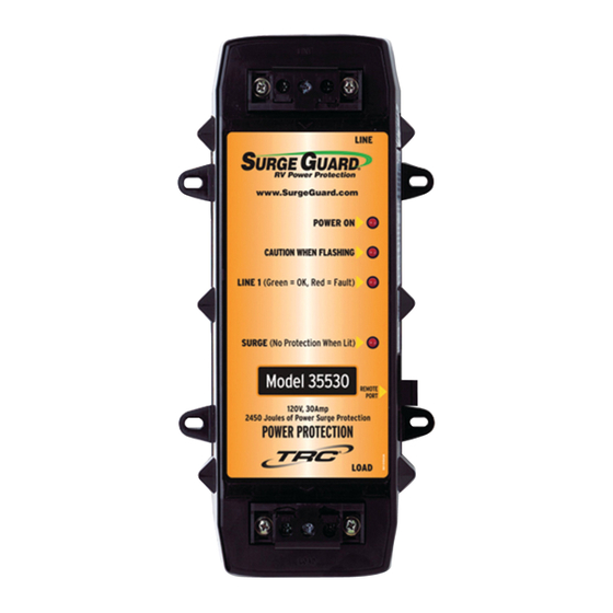
MODEL 35530
HARDWIRE
LINE
www.SurgeGuard.com
POWER ON
CAUTION WHEN FLASHING
LINE 1
(Green = OK, Red = Fault)
SURGE (No Protection When Lit)
Model 35530
120V, 30 Amp
2450 Joules of Power Surge Protection
POWER PROTECTION
LOAD
FOR YOUR RECORDS
MODEL NO: ___________________
DATE PURCHASED: ____________
WHERE PURCHASED: __________
www.SurgeGuard.com
INSTALLATION & OPERATING
INSTRUCTIONS
OVER/UNDER VOLTAGE PROTECTION
Should voltage drop below 102V or rise above 132V for more than 8-14
seconds, power to RV is turned off.
SEE TIME DELAY INDICATOR
(with cover) INPUT TERMINALS (cover not required)
3 MODE SURGE PROTECTION
Protects
the
systems and
damaging power surge events without power
interruptions to the RV.
INPUT POWER INDICATION
The green LED indicates power to RV when
illuminated.
LINE
TIME DELAY AND FAULT INDICATOR
When unit is plugged in, the red caution LED
is flashing indicating delay of 128 seconds.
(This allows head pressure to bleed off the A/C
compressor). Flashing can indicate faults are
present, like possible mis-wiring or current to
ground conditions (will prevent power reset).
When green light is on L1 is between
102VAC to 132VAC. When the light is red,
L1 is greater than 132VAC or below 102VAC,
and power is shut off to protect your coach.
When green light is on L2 is between
102VAC to 132VAC. When the light is red,
L2 is greater than 132VAC or below 102VAC,
REMOTE
and power is shut off to protect your coach.
PORT
If the red "SURGE" indicator LED is on, it
means that the built-in surge protection has
LOAD
been sacrificed to protect your equipment
and is no longer functioning properly. Other
features will still function, but the unit is
recommended to be replaced.
Connection for optional Remote LCD display
PN 40298 (sold separately).
Caution: Use 6-pin cable only.
(with cover) OUTPUT TERMINALS (cover not required)
TECHNOLOGY RESEARCH, LLC
A Southwire Company
5250 140th Avenue North ▪ Clearwater, Florida 33760
RV's
sensitive
electronic
appliances from potentially
L1 VOLTAGE
L2 VOLTAGE
SURGE FAILURE
REMOTE PORT
(727) 535-0572
MODEL 35550
HARDWIRE
LINE
www.SurgeGuard.com
POWER ON
CAUTION WHEN FLASHING
LINE 1
(Green = OK, Red = Fault)
LINE 2
(Green = OK, Red = Fault)
SURGE (No Protection When Lit)
Model 35550
REMOTE
PORT
120/240V, 50 Amp
3850 Joules of Power Surge Protection
POWER PROTECTION
LOAD
PLEASE READ THE ENCLOSED
INSTRUCTIONS CAREFULLY.
In the event you have any questions
concerning the care of this product,
please contact Customer Support.
505-00115A
1
Advertisement
Table of Contents

Summary of Contents for TRC Surge Guard 35530
- Page 1 www.SurgeGuard.com MODEL 35550 MODEL 35530 HARDWIRE HARDWIRE INSTALLATION & OPERATING INSTRUCTIONS OVER/UNDER VOLTAGE PROTECTION Should voltage drop below 102V or rise above 132V for more than 8-14 seconds, power to RV is turned off. SEE TIME DELAY INDICATOR (with cover) INPUT TERMINALS (cover not required) 3 MODE SURGE PROTECTION Protects RV's...
- Page 2 INSTALLATION INSTRUCTIONS WARNING: This Surge Guard device must be installed by a licensed electrician or by an RV dealer. PROTECTING SOURCE POWER ONLY PROTECTING SOURCE AND GENERATOR POWER Disconnect RV power cord from source power. Disconnect RV power cord from source power. Locate the Surge Guard in the RV's electrical compartment.
- Page 3 VOLTAGE REGULATOR on the line side. conductors. If using Surge Guard with TRC Voltage Regulator (10175 or 10176) the Open ground circuit on Move RV to new voltage regulator should be positioned between the power pedestal (shore the line side electrical source.
- Page 4 www.SurgeGuard.com MODÈLE 35550 MODÈLE 35530 RACCORDEMENT FIXE RACCORDEMENT FIXE INSTALLATION ET FONCTIONNEMENT INSTRUCTIONS PROTECTION CONTRE LES SURTENSIONS / SOUS-TENSIONS Si la tension est inférieure à 102 V ou supérieure à 132 V pendant plus de 8 à 14 secondes, le courant au VR est coupé. VOIR LE TEMPORISATEUR (avec couvercle) BORNES D’ENTRÉE (couvercle non requis) 3 MODE DE PROTECTION CONTRE...
- Page 5 INSTRUCTIONS D’INSTALLATION AVERTISSEMENT : Ce dispositif de protection contre les surtensions doit être installé par un électricien agréé ou un concessionnaire de VR. PROTECTION DE LA SOURCE D’ÉNERGIE UNIQUEMENT PROTECTION DE LA SOURCE D’ÉNERGIE ET DE LA GÉNÉRATRICE Débrancher le cordon d’alimentation du VR de la source d’énergie. Débrancher le cordon d’alimentation du VR de la source d’énergie.
- Page 6 Si vous utilisez un dispositif de protection contre les surtensions avec un L1 et/ou L2 s’allume Alimentation partielle Utiliser une régulateur de tension TRC (10175 ou 10176), le régulateur de tension doit en rouge ou est uniquement à la source nouvelle source être placé...
- Page 7 TROUBLESHOOTING GUIDE Model 35550 50A Hardwire Surge Guard with Optional ® Remote LCD Display Surge Guard protects your RV from low quality or incorrect shore power. LINE Normally shore power should be around 115 –120 Volts AC from L1 or L2 to Neutral, or 240V from L1 to L2. When power falls too far outside this range it represents a poor or hazardous condition to your RV’s electrical system.
- Page 8 Optional Remote Display shows "NEUTRIP" This indicates current on neutral return over 65A. L1 and L2 are within range (102 – 132VAC) Please call TRC Technical Support at 1-800-780-4324 and there is no power. Surge Failure Light is on. If the red “SURGE” indicator LED is on, it means that the built-in surge protection has been sacrificed to protect your equipment and is no longer functioning properly.
- Page 9 GUIDE DE DÉPANNAGE Modèle 35550 Dispositif à raccordement fixe de 50 A Surge Guard avec ® affichage ACL à distance en option Le dispositif de protection contre les surtensions protège votre VR d’un courant de stationnement incorrect ou de mauvaise qualité. LIGNE Normalement le courant de stationnement est de 115 –120 Volts CA de L1 ou L2 à...
- Page 10 Cela signifie que le courant sur le fil neutre est de nouveau supérieur à 65 A. L1 et L2 sont dans la plage (102 – 132 V CA) Veuillez appeler l’assistance technique TRC au 1-800-780-4324 et il n’y a pas de courant.
- Page 11 Scenario: You lose shore power for no obvious reason. If you have a TRC Surge Guard unit, the following procedures will help you determine whether you have a problem with your Surge Guard, in your coach electrical system, or an external power problem.
- Page 12 When your unit is installed, verify (or have your installer verify) and record voltages as indicated below, preferably under your normal operating conditions. This could assist you in locating a problem, in the event you lose power later. If you have the experience to do it yourself, you will need a suitable AC voltmeter.
- Page 13 * For the Model 40240 Remote, record all readings, note any fault conditions. Additional voltage checks for 50A Models 34560 and 40240 Hard Wired Surge Guards: At the Surge Guard input: D) L1 ________ L2 ________(Voltages at input) Verify and record the voltage at the input to the Surge Guard: white to black wires (L1), white to red wires (L2). E) ________(Voltage) Verify that you have 0 volts between the white wire (neutral) and the green wire (ground).
- Page 14 If you have questions regarding your Surge Guard units, Automatic Transfer Switch or Voltage Regulators, please contact TRC’s technical support at 800-780-4324 during normal business hours, Eastern Time. You may also contact TRC through our websites at www.SurgeGuard.com and www.trci.net, or email at productinfo@trci.net If you require a replacement unit, check your local RV supplier.
Need help?
Do you have a question about the Surge Guard 35530 and is the answer not in the manual?
Questions and answers