Advertisement
Table of Contents
- 1 Table of Contents
- 2 Specifications
- 3 Major Components
- 4 Nozzles Direction
- 5 Working Principles
- 6 Safety Precautions
- 7 Maintenance
- 8 Flow Rate Diagram
- 9 Machine Parts Diagram
- 10 Exploded Parts List
- 11 Metering Valve Parts Listing
- 12 Electrical Schematics
- 13 Noise Level Comparison
- Download this manual
Advertisement
Table of Contents

Subscribe to Our Youtube Channel
Summary of Contents for Dyna-Fog Hurricane Ultra 2794
- Page 1 HURRICANE ULTRA ULV/Mist Sprayer MODEL 2794 & 2796 OPERATION AND MAINTENANCE MANUAL...
-
Page 2: Table Of Contents
TABLE OF CONTENTS Specifications .. 3 Major Components Nozzles Direction ... 4 Working Principles Safety Precautions . . 6 Maintenance Flow Rate Diagram Machine Parts Diagram ..10 Exploded Parts List . 11 Metering Valve Parts Listing ..12 Electrical Schematics .... -
Page 3: Specifications
SPECIFICATIONS ELECTRIC BLOWER MOTOR: MODEL 2794: CONTINUOUS DUTY 110-130 VOLTS AC WEIGHT: 6.85 AMPS EMPTY 6.3 lbs. 2.9 kg 60/60 Hz. FULL 14.3 lbs. 6.5 kg 20,000 RPM SHIPPING INFORMATION: DIMENSIONS 13.5 x 11 x 17 in 34.3 x 27.9 x 43.2 cm MODEL 2796: WEIGHT 9.0 lbs. -
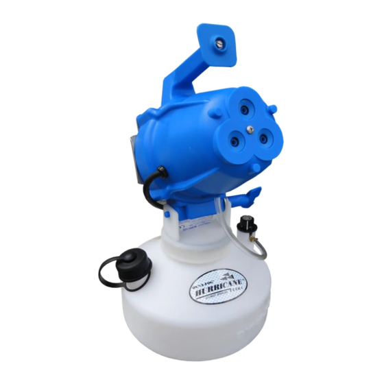
Page 4: Major Components
MAJOR COMPONENTS NOZZLES DIRECTION The machine allows adjusting the angle in a 60° range, up to 40° above horizontal, and -20° belo w horizontal. Use the Locking Handle to adjust the angle. -
Page 5: Working Principles
The machine consists of a motor/blower assembly, a nozzle system, nozzle housing, a formulation tank and a metering valve. The various components are identified in a diagram below. The blower is a single stage/centrifugal impeller/axial flow driven by a universal motor operating at a speed of about 20,000 RPM. -
Page 6: Safety Precautions
SAFETY PRECAUTIONS WARNING READ UNDERSTAND THESE SAFETY PRECAUTIONS BEFORE OPERATING MACHINE. FAILURE PROPERLY FOLLOW THESE PRECAUTIONS MAY LEAD TO A FIRE, EXPOSION OR ELECTRIC SHOCK HAZARD. ELECTRIC POWER. This machine uses electrical power at common commercially available voltages. When directly contacted, such voltages are hazardous to human life. - Page 7 Where a high flash point or “no” flash point liquid formulation will ignite far less readily than a low flash point liquid and for this reason is strongly advocated. The higher or “no” flash point formulation can ignite if the proper conditions exist. These conditions are basically two: 1.
-
Page 8: Maintenance
DO NOT Do not Spray flammable liquids near open flame or other source of ignition. Do not Use a machine that is broken or damaged in any way. Do not Alter the machine by adding or removing parts. Do not Restrict the motor blower inlet area. Do not Tamper with the output nozzle. -
Page 9: Flow Rate Diagram
Turning the Knob of the Metering Valve regulates the Flow Rate. If the Knob is rotated clockwise, the flow rate will be reduced. If the Knob is rotated counterclockwise, the flow rate will be increased. As reference, the average flow rate is shown in the bottom table at three differen t positions of the Metering Valve knob when using water. -
Page 10: Machine Parts Diagram
N O T E : T H E F R IC T IO N W A S H E R S H O U LD B E L O C A T E D B E T W E E N T H E T W O P L A S T IC... -
Page 11: Exploded Parts List
HURRICANE ULTRA PARTS LIST ITEM PART NUMBER ITEM DESCRIPTION 62130-10 TANK, 1G ROUND 63156 LABRL, HURR LOGO 62135-1 CAP AY, TANK BLUE 62131-1 CLEVIS, BLOWER BLUE 62151-1 LABEL, HURR (RT) 115V 62151-2 LABEL, HURR (RT) 230V 20180-3 STRAIN CONNECTOR (115V) 20180-4 STRAIN CONNECTOR (203V) 62031-2... -
Page 12: Metering Valve Parts Listing
VALVE ASSEMBLY, BRASS (P/N: 62195) ITEM QTY. PART NUMBER DESCRIPTION 32692-1 NUT, PACKING, BRASS 32690 WASHER, PACKING 32691 WASHER, BRASS 62319-1 STEM, VALVE 62180 VALVE BODY/BARB AY. 10100-110 O-RING 62227-1 TUBE, BLUE, 3/16 ID. X 5.16 OD. 80408 FILTER, LONG TAPER, 130 MICRONS VALVE ASSEMBLY, SPARE PARTS KIT (P/N: 62185) -
Page 14: Noise Level Comparison
NOISE LEVEL COMPARISON TYPICAL SOUND TYPICAL MUSIC SPL, Db Chest wall vibrates, chiking, giddiness Jet taking off, 25 meters Threshold of pain Artillery, 100 yards Cannon (peaks) Pneumatic chipper Riveter, nearby Loud car horn, nearby Very loud rock (peaks) Very loud classical (peaks) Pain Threshold Inside N.Y. - Page 15 Dyna-Fog Offers a Complete Assortment of Sprayers and Foggers PULSE-JET POWERED THERMAL FOGGERS: From 0-120 GPH (0-453 LPH) output. Our complete line include different models like the Superhawk, Golden Eagle, Trailblazer, Falcon, Patriot, Blackhawk, Mister III, SilverCloud and Model 1200. Portable or Truck mounted machines. Different models are available for Oil base or Water base formulations.
Need help?
Do you have a question about the Hurricane Ultra 2794 and is the answer not in the manual?
Questions and answers